Commissioning
EL47xx
113
Version: 2.7
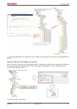
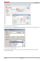
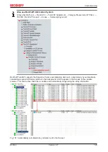
Fig. 139: Set up the link of the PLC array variable (left: for the last preceding paragraph Step 2a, right: for the
last preceding paragraph Step 2b)
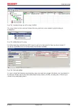
Fig. 140: Select the EL3773 PDO "L1 Voltage Samples" to create a link to the PLC array variable
„aUI_Samples“
The selection of PDO "U1 Samples" of the EL3773 for “MAIN.aUI_Samples” based by the last preceding
paragraph Step 2a as illustrated above have to be done in the same way for “Var 1” accordingly.
Step 4: Selection of the PLC array variable for the Y-axis of the scope
Now the configuration will be activated (
) and logged in the PLC (
), so the array variable will be
visible for the target browser of the scope for being selected.
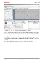
Thereby the drop down menu will be opened by right clicking on “Axis” (A) for selection of the scope features
(B):
Summary of Contents for EL47 Series
Page 1: ...Documentation EL47xx Analog output terminal with oversampling 2 7 2020 02 27 Version Date...
Page 2: ......
Page 33: ...Mounting and wiring EL47xx 33 Version 2 7 Fig 23 Other installation positions...
Page 70: ...Commissioning EL47xx 70 Version 2 7 Fig 73 Incorrect driver settings for the Ethernet port...
Page 149: ...Commissioning EL47xx 149 Version 2 7 Fig 184 Process data tab SM1 EL47xx...


