background image

Commissioning

Real-time Ethernet port multiplier

47

Version: 2.6

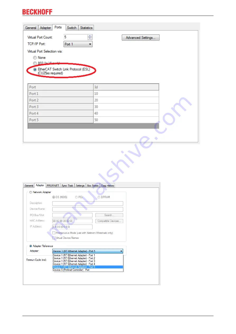
Fig. 63: Selection of the "Virtual Port" setting

Setting of the PROFINET Device or Controller adapter

Once the CU2508 has been activated as Multiple Protocol Handler in the system and the relevant ports have
been enabled, you can select an "Adapter Referent" under the "Adapter" tab for the Controller or the Device.
Enter the port through which you want to operate PROFINET.

Fig. 64: Selecting the "Adapter Referent"

No other special considerations are required for the CU2508; you can proceed as usual.

Summary of Contents for CU2508

Page 1: ...Documentation CU2508 Real time Ethernet port multiplier 2 6 2020 05 19 Version Date...

Page 2: ......

Page 3: ...sioning 29 4 1 Setting up under TwinCAT 2 11 29 4 2 Port definition TwinCAT 2 11 32 4 2 1 Setup Device EtherCAT 32 4 2 2 Setting up Device EtherCAT with cable redundancy 37 4 2 3 Setting up Device Eth...

Page 4: ...Table of contents Real time Ethernet port multiplier 4 Version 2 6...

Page 5: ...the modification of products that have already been supplied may be made on the basis of the data diagrams and descriptions in this documentation Trademarks Beckhoff TwinCAT EtherCAT EtherCAT G Ether...

Page 6: ...tended for trained specialists in control automation and drive engineering who are familiar with the applicable national standards Description of instructions In this documentation the following instr...

Page 7: ...pdate structure 2 1 Chapter Portdefinition TwinCAT 2 11 updated Chapter Technical data updated Update structure 2 0 Migration 1 8 Update chapter LEDs and connection Update structure 1 7 Addenda chapte...

Page 8: ...CAT Slave Information in the form of an XML file which is available for download from the Beckhoff web site From 2014 01 the revision is shown on the outside of the IP20 terminals see Fig EL5021 EL te...

Page 9: ...y for this PCB hardware version of I O PCB 1 Unique serial number ID ID number In addition in some series each individual module has its own unique serial number See also the further documentation in...

Page 10: ...r Fig 4 EL3202 0020 with serial batch number 26131006 and unique ID number 204418 Fig 5 EP1258 00001 IP67 EtherCAT Box with batch number date code 22090101 and unique serial number 158102 Fig 6 EP1908...

Page 11: ...multiplier 11 Version 2 6 Fig 7 EL2904 IP20 safety terminal with batch number date code 50110302 and unique serial number 00331701 Fig 8 ELM3604 0002 terminal with unique ID number QR code 100001051...

Page 12: ...pending on the product it can be found in the following places on the packaging unit directly on the product if space suffices on the packaging unit and the product The BIC is machine readable and con...

Page 13: ...ata identifiers are used by Beckhoff and serve internal processes Structure of the BIC Example of composite information from item 1 to 4 and 6 The data identifiers are marked in red for better display...

Page 14: ...and sent to the PC With the aid of a driver users have eight independent ports with full real time characteristics available The CU2508 is used in applications in which several Ethernet ports are req...

Page 15: ...N 61000 6 2 EN 61000 6 4 Protection class IP20 Installation position variable Approval CE cULus 28 2 3 Technology Introduction As a port multiplier that is as transparent as possible the CU2508 extend...

Page 16: ...e used in each TwinCAT system Fig 11 Principle CU2508 topology Downlink Port characteristics The default setting of the CU2508 is optimized for use with EtherCAT downlinks especially for EtherCAT IO r...

Page 17: ...gered basis also referred to as FreeRun mode and the output times are essentially dependent on frame delays jitter for example 2 Time controlled sending time stamped receiving with frame influence no...

Page 18: ...ccount Example An EtherCAT system is installed at ports X1 and X2 each with an EL2202 as output terminal The edges are to be measured with an oscilloscope for demonstration purposes In system X1 the b...

Page 19: ...ort is supplemented by receipt information receiving port time and forwarded to the controller via the uplink The local hardware based clock in the CU2508 then controls the sending of the frames with...

Page 20: ...ng others Multi EtherCAT adapter 32 Up to 8 independent EtherCAT systems can be created Synchronized EtherCAT systems 32 If the CU2508 is selected as the ReferenceClock the EtherCAT systems connected...

Page 21: ...TCP IP frames from the connected EtherCAT systems Fig 17 Use of the CU2508 as an Ethernet multi protocol handler with EtherCAT and TCP IP Real time fieldbus on non real time controller If an Ethernet...

Page 22: ...te instead of 8 kbyte for EtherCAT segments with particularly high data transfer rates High data traffic is generated by IO systems with many cyclical data e g when many subscribers over 100 and or su...

Page 23: ...W x H x D CU2508 approx 146 5 mm x 100 mm x 38 m Space requirement in the control cabinet The RJ45 connector increase the depth depending on their design and the Ethernet cable used Above the mountin...

Page 24: ...the mounting rail to the planned assembly location Suspend the switch on the mounting rail with the spring on the lower side of its latching flange Press the switch upwards 1 Press the upper side of t...

Page 25: ...ersion 2 6 Fig 22 Removal 3 2 1 Diagnostic LEDs The CU2508 has 4 diagnosis LEDs Fig 23 CU2508 front view The CU2508 currently has no further diagnostic features 3 3 Cabling Power supply Pin configurat...

Page 26: ...ource must not be connected in series or parallel with another NEC class 2 voltage source These requirements apply to the supply of all Bus Cou plers power supply terminals Bus Terminals and their pow...

Page 27: ...r channels and the distributed clocks Outputs remain in safe state on State of the EtherCAT State Machine OP normal operating state mailbox and process data communication is possible Int Act green fla...

Page 28: ...d EtherCAT Sys tem only Examination For cULus examination the Beckhoff I O System has only been investigated for risk of fire and electrical shock in accordance with UL508 and CSA C22 2 No 142 For dev...

Page 29: ...ML files must then be observed Setting up Append a new device in the TwinCAT System Manager with a right click Fig 28 Appending a new device Select the Real Time Ethernet Adapter Multiple Protocol Han...

Page 30: ...adapter is now operated in ConfigMode with this cycle time i e usually 250 cycles sec Promiscuous Mode If activated the Ethernet Frames are copied from the real time context into the Windows NDIS laye...

Page 31: ...ink ports can now be assigned to protocols the TCP IP behavior of the CU2508 can be set Diagnosis The TwinCAT System Manager provide several information about the online operation Fig 34 Statistics Na...

Page 32: ...an EtherCAT device In EtherCAT operation the CU2508 downlink port used is not transparent but appears as a Distributed Clocks capable EtherCAT slave in the configuration As a result it can appear as...

Page 33: ...evice Fig 37 Selection of the EtherCAT device The desired downlink port of the CU2508 can now be selected Fig 38 Selection of the CU2508 port The device Device 2 EtherCAT is now connected according to...

Page 34: ...an EtherCAT slave and can be scanned or created manually Fig 40 Appending a CU2508 EtherCAT slave If creating manually the CU2508 Ethernet port CU2508 0000 must be selected The check box ExtendedInfor...

Page 35: ...508 port is not marked as Distributed Clocks capable hence under TwinCAT the next subsequent Distributed Clocks capable slave is selected as the ReferenceClock In each case the CU2508 port is the 1st...

Page 36: ...ttings Ethernet over EtherCAT If devices with EoE support are used in a lower level EtherCAT system this affects the settings of the EoE switch in the CU2508 if this is configured for EoE transport Re...

Page 37: ...EtherCAT system documentation The combination of the EtherCAT cable redundancy and Distributed Clocks technologies is possible using the CU2508 Notes on EtherCAT cable redundancy Only the downlink po...

Page 38: ...isplayed in the Device EtherCAT using the Topology button see fig Display of a simple EtherCAT topology Fig 47 Display of a simple EtherCAT topology The items below are to be specified in the followin...

Page 39: ...umber of ports must be set to available in the settings for the CU2508 adapter After specifying the redundancy adapter it must be checked whether the System Manager has selected the correct EtherCAT s...

Page 40: ...ata communication The Windows operating system manages TCP IP communication with its Ethernet adapters in the so called NDIS network mediation layer The adapter settings can be accessed via the Window...

Page 41: ...CU2508 downlink port as a TCP IP port the address area is under the IP mask 255 255 0 0 therefore all devices must have an IP address from the area 192 168 x x These settings are changed via the Wind...

Page 42: ...ig Flow of data when using the CU2508 as an EoE switch A IP routing is a function inherent to the operating system for the mediation of IP telegrams even between networks that do not lie in the same s...

Page 43: ...case of embedded CX systems under Windows CE WEC via the CX config tool If activated the NDIS network layer also mediates IP packets whose IP addresses do not correspond to the subnet mask 4 2 4 Setti...

Page 44: ...red the target platform can be selected via TargetType Not an actual port of the PC but rather a virtual adapter of the CU2508 is then merely selected as the Ethernet adapter for the CU2508 Fig 57 Sel...

Page 45: ...er must be created in the configuration in order to operate a CU2508 downlink port as an EAP real time Ethernet interface for IO devices BK90xx EK90x The EAP EtherCAT Automation Protocol is operated h...

Page 46: ...evice slave or controller master supplement with the CU2508 However you can use only one controller or device if they are in a unique network If the networks a physically separated it is possible to u...

Page 47: ...8 has been activated as Multiple Protocol Handler in the system and the relevant ports have been enabled you can select an Adapter Referent under the Adapter tab for the Controller or the Device Enter...

Page 48: ...e Ethernet driver for TwinCAT must be installed Publisher Subscriber model In the Publisher Subscriber model the Publisher makes variables available Subscribers can subscribe to a variable The Publish...

Page 49: ...2 Configuration of the Publisher In the TwinCAT System Manager a new box is added for the Publisher under the RT Ethernet device Insert a Publisher Box A Publisher box must be added under the RT Ether...

Page 50: ...inputs and outputs of the added Publisher box The FrameState input under the box indicates the current status of the sent Ethernet frames The following values are possible for the FrameState Short des...

Page 51: ...ossible for VarState Short description Value Description Not sent variable skipped 0x0001 A Control Word can be written in the VarCtrl output under the network variable The following values are possib...

Page 52: ...r the Subscriber under the RT Ethernet device Adding a Subscriber box and linking the network variables A Subscriber box must be added under the RT Ethernet device Fig 70 Insert a Subscriber box under...

Page 53: ...6 Fig 72 Creating the network variable under the Subscriber box Fig 73 Adding a network variable The link to a Publisher variable can be created automatically First you need to find the Publisher comp...

Page 54: ...sher variables Inputs and outputs were created under the added variable Fig 75 Display of created inputs and outputs The FrameState input and the FrameCtrl output under the box indicate the current st...

Page 55: ...d on the Subscriber side Two input variables are available for this purpose under the network variable The Quality variable provides a counter with a resolution of 100 s The counter value indicates th...

Page 56: ...net telegram between two Ethernet cable ends is determined by the source MAC and the destination MAC The Ethernet telegram is identified as Beckhoff real time Ethernet by the Ethertype 0x88A4 As a rea...

Page 57: ...ber e g 10 ms a slow Publisher e g 100 ms leads to poor connection quality as reported by the diagnostic variable Quality Dynamic temporary blocking of sending a Publisher must also be taken into acco...

Page 58: ...s PC2 subscriber2 not only re ceives the designed ID 8 variable from PC1 Publisher2 but since it is sent as a broadcast it also receives the NWV from PC3 Publisher1 Differentiation is then no longer p...

Page 59: ...byte variables must lie at an address that is divisible by 4 then all 2 byte variables must lie at an address that is divisible by 2 then all 1 byte variables Further recommendations if STRING x is us...

Page 60: ...ve another unique MAC address Please refer to the relevant literature for further rules relating to the formation of multicast MAC IP addresses Unicast Either direct entry of the destination MAC or vi...

Page 61: ...ulticast Unicast Specify the target device e g 192 168 0 1 making sure that it can be reached through the subnet mask Use of broadcast and multicast Network variables sent as broadcast or multicast at...

Page 62: ...rameState variable Note ARP handling ARP Address Resolution Protocol allocation of hardware MAC addresses to network addresses IP is managed by the operating system Windows Disable Subscriber Monitori...

Page 63: ...ox Fig 84 Subscriber settings Settings Receiving Options Only permits NWVs from a certain publisher for this subscriber Multicast Configuration ditto Process data VarId If activated the variable ID ca...

Page 64: ...cally via PLC where appropriate Ignore Data Type Hash Hash calculation is currently not supported Process data Quality See explanatory notes above CycleIndex This index is incremented with each succes...

Page 65: ...ESL prefix The ESL data are structured as follows Fig 87 ESL structure Ethernet network monitors The freely available network monitor Wireshark has contained an interpreter for the ESL protocol since...

Page 66: ...net port on the master PC and connect the power supply The port must be set up as a real time port with the Beckhoff TwinCAT driver The downports X1 8 must not be connected Fig 89 CU2508 structure 4 C...

Page 67: ...f this a previously hidden element the CU2508 configuration port becomes visible in this case CU2508 0000 0016 Fig 94 Selection of the CU2508 0000 configuration port Select this device The configurati...

Page 68: ...Fig 95 Online configuration Instruction TwinCAT 3 The procedure is the same as for TwinCAT 2 add the CU2508 Configuration Port to the selected EtherCAT adapter Fig 96 Append Configuration Port Then ch...

Page 69: ...FW version On the basis of fig Online configuration EtherCAT ESI revision controller and FPGA FW can now be checked ESI Revision When the system is running in ConfigMode the revision found can be dis...

Page 70: ...on in this case 01 is displayed in the index 0x100A D Note that in C OnlineData green is displayed Fig 100 Reading out the controller firmware version FPGA firmware rbf Select device CU2508 A press Ad...

Page 71: ...if communication is working perfectly an update of ESI controller and FPGA firmware can be performed by right clicking on the CU2508 device Fig 102 Update by right clicking ESI XML update The ESI xml...

Page 72: ...to set some of the CU2508 s properties The CU2508 slaves running in regular EtherCAT op eration always report with revision 0000 and cannot be programmed separately Fig 104 Display of the revision 000...

Page 73: ...erview below shows the hardware versions on which a firmware can be operated Note It is recommended to use the newest possible firmware for the respective hardware Beckhoff is not under any obligation...

Page 74: ...ckhoff products and system solutions Beckhoff s branch offices and representatives Please contact your Beckhoff branch office or representative for local support and service on Beckhoff products The a...

Page 75: ...Fax 49 5246 963 9157 e mail support beckhoff com Beckhoff Service The Beckhoff Service Center supports you in all matters of after sales service on site service repair service spare parts service hotl...

Page 76: ...y 18 Fig 14 CU2508 Uplink Delay 19 Fig 15 Different IP data traffic depending on the setting 20 Fig 16 Use of the CU2508 as an EtherCAT cable redundancy star point 21 Fig 17 Use of the CU2508 as an Et...

Page 77: ...Virtual Port setting 47 Fig 64 Selecting the Adapter Referent 47 Fig 65 Publisher Subscriber model 48 Fig 66 Insert a Publisher Box 49 Fig 67 Insert a Network Variable 50 Fig 68 Displaying the inputs...

Page 78: ...U2508 0000 configuration port 67 Fig 95 Online configuration 68 Fig 96 Append Configuration Port 68 Fig 97 Check for lost frames and State OP 69 Fig 98 Display revision after scan 69 Fig 99 Display di...

Reviews: