Installation and Operating instructions for
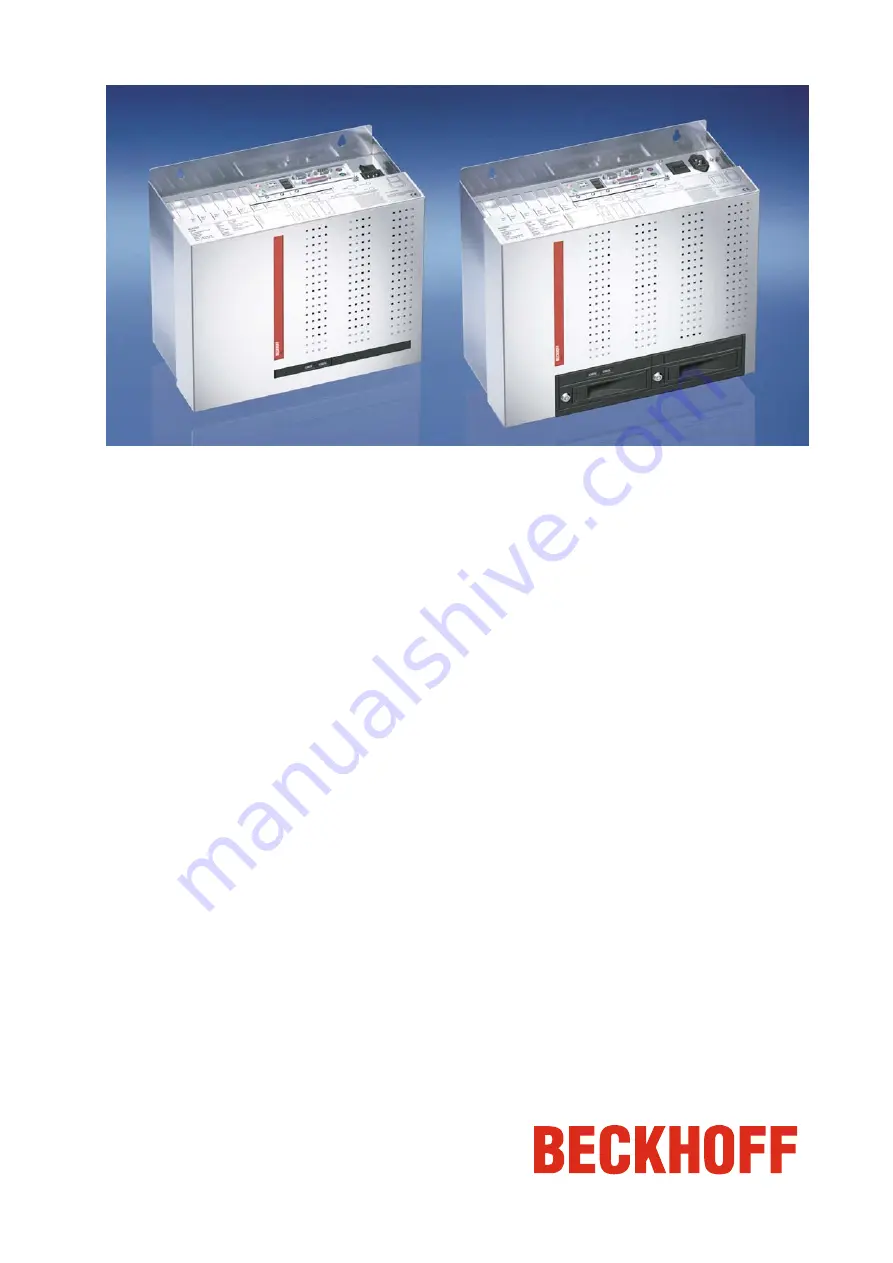
Control Cabinet Industrial PC C6640, C6650
Version: 1.1
Date: 2010-04-08
Page 1: ...Installation and Operating instructions for Control Cabinet Industrial PC C6640 C6650 Version 1 1 Date 2010 04 08...
Page 2: ......
Page 3: ...1 Earthing measures 11 Power Supply Connection with 100 240 VAC power supply unit 12 Mains Socket 12 Power supply cords 12 Power Supply Connection with 24 VDC power supply unit optional 13 Beckhoff po...
Page 4: ...arters 23 Beckhoff Support 23 Beckhoff Service 23 Assembly dimensions 24 C6640 Configuration with 100 240 VAC Power Supply 24 C6640 Configuration with 24 VDC Power Supply optional 25 C6650 Configurati...
Page 5: ...meaning of 443 BGB of the German Civil Code or a statement about the contractually expected fitness for a particular purpose in the meaning of 434 par 1 sentence 1 BGB In the event that it contains te...
Page 6: ...he plant Pulling out the fieldbus connection plug uncouples the PC optional Items of equipment that have been switched off must be secured against being switched on again The Industrial PC s power sup...
Page 7: ...al regulations depending on the machine type Depending on the type of machine and plant in which the Industrial PC is being used there will be national regulations for the control of such machines and...
Page 8: ...applications Opening the Housing View of the C6650 configuration with 100 240 VAC power supply The housing cover is locked by a latch After pressing the key 1 the cover can be fold up a little in the...
Page 9: ...ing cover Now the housing cover can be taken off completely so providing access to the components The reassembly of the cover takes place in reverse order Ensure that the cover engages into the slides...
Page 10: ...configuration options of the motherboard are available Order option Intel Celeron M Intel Pentium M Intel Core Duo Intel Core 2 Duo Intel Core 2 Quad C6640 0000 1 5 GHz 1 8 GHz C6640 0010 2 0 GHz 2 1...
Page 11: ...interfaces USB1 USB4 The four USB interfaces X108 X111 are used to connect peripheral devices with USB connections The USB2 0 standard is supported Network connection 10 100MBit Network 10 100MBit Th...
Page 12: ...in temperature make sure that moisture condensation does not form on or inside the device Prior to operation the unit must be allowed to slowly adjust to room temperature Should condensation occur a d...
Page 13: ...bove and below the housing must be at least 50 mm in order to ensure adequate ventilation of the PC Warning Extreme environmental conditions should be avoided as far as possible Protect the PC from du...
Page 14: ...at the PC housing main switch mains socket Power supply cords Power cords Europe In the area Europe you use the provided cable with inlet connector for non heating apparatus to connect the Industrial...
Page 15: ...ach addresses this problem and now offers the user the option of switching the PC off without the need for using the battery thereby reducing the load on the battery In addition to the main switch thi...
Page 16: ...ower supply unit Current loading maximum 5 V 14 A 5 V 0 3 A 12 V 12 A 12 V 0 5 A 3 3 V 12 A 5 V VSB 1 5 A Pin assignment of the connectors Two 5 pin plug connectors with CAGE CLAMP connection see phot...
Page 17: ...terials for assembly of the connector Female plug connector 5 pole Strain relief housing 1 2 3 4 5 A B C D Fitting the connector Fitting the connector to the cable The plug is fitted to the cable as f...
Page 18: ...C_ON signal is inverted i e the PC shuts down if the 24 V connection is live If the PC_ON input is NOT connected by the user the PC can be booted in the familiar way by connecting the supply voltage a...
Page 19: ...g to the wiring diagram the circuit of PC_ON and Power Status is symbolical Wiring diagram power supply and external switch i Note The battery pack can only be connected when the Industrial PC is prov...
Page 20: ...ndustrial PC and to the devices that are to be connected Connect all data transfer cables if present to the appropriate plug in receptacles of the data telecommunication networks Reconnect all devices...
Page 21: ...Warning First shut down then switch off the PC If the Industrial PC is switched off as the software is writing a file to the hard disk the file will be destroyed Control software typically writes som...
Page 22: ...sion if battery is incorrectly replaced Replace only with same or equivalent type recommended by the manufacturer Dispose of used batteries according to the manufacturer s instructions Replacing the f...
Page 23: ...Industrial PC On delivery of the Beckhoff Industrial PC with operating system the software is already installed Should the software not be installed on your PC the drivers can be installed from the dr...
Page 24: ...d press any key Check the setup settings Call Beckhoff Service Computer boots software starts but control does not operate correctly Cause of the fault is either in the software or in parts of the pla...
Page 25: ...tra e 5 33415 Verl Germany Phone 49 0 5246 963 0 Fax 49 0 5246 963 198 e mail info beckhoff com Beckhoff Support Beckhoff offers you comprehensive technical assistance helping you not only with the ap...
Page 26: ...sions The following pages show diagrams of the Industrial PC with dimensions in mm C6640 Configuration with 100 240 VAC Power Supply Warning The assembly of the unit must take place with the orientati...
Page 27: ...Assembly dimensions C6640 Configuration with 24 VDC Power Supply optional Warning The assembly of the unit must take place with the orientation diagrammed here C6640 C6650 25...
Page 28: ...Assembly dimensions C6650 Configuration with 100 240 VAC Power Supply Warning The assembly of the unit must take place with the orientation diagrammed here 26 C6640 C6650...
Page 29: ...Assembly dimensions C6650 Configuration with 24 VDC Power Supply optional Warning The assembly of the unit must take place with the orientation diagrammed here C6640 C6650 27...
Page 30: ...61000 6 2 Emitted resistance according to EN 61000 6 4 Transport and storage The same values for atmospheric humidity and shock resistance are to be observed during transport and storage as in operat...