background image


Drive Technology 

3 Safety


AM3100 Version: 

1.4 

3.2 

Special safety instructions for AM3100 

The safety instructions are designed to avert danger and must be followed during installation, commissioning, 
production, troubleshooting, maintenance and trial or test assemblies. 
The servomotors of the AM3100 series are not designed for stand-alone operation and are always installed in a 
machine or system. After installation the additional documentation and safety instructions provided by the 
machine manufacturer must be read and followed. 


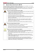
WARNING 

Serious risk of injury through high electrical voltage! 


Never open the servomotor when it is live. Opening the device would invalidate any warranty 
and liability claims against Beckhoff Automation GmbH. 


Negligent, improper handling of the servomotor and bypassing of the safety devices can lead 
to personal injury or death through electric shock. 


Ensure that the protective conductor is connected properly. 


The machine manufacturer must prepare a hazard analysis for the machine, and must take 
appropriate measures to ensure that unexpected movements can not lead to injury to 
persons or to material damage. 


Power leads may be live, even if the motor is not running. Never undo the electrical 
connections to the motor when it is live. Under unfavourable conditions arcing may occur, 
resulting in injury and damage to contacts. 


Disconnect the servomotor from the servo terminal and secure it against reconnection. 


WARNING 

Serious risk of injury through hot surfaces! 


The surface temperature may exceed 50 °C, resulting in a risk of burns. 


Avoid touching the housing during or shortly after operation. 


Leave the servomotor to cool down for at least 15 minutes after it is switched off and use a 
thermometer to check whether the surface has cooled down sufficiently. 


Attention 

Danger for persons, the environment or equipment 


Carefully read this manual before using the servomotor thoroughly, paying particular 
attention to the safety instructions. In the event of any uncertainties please notify your sales 
office immediately and refrain from working on the servomotor. 


Only well trained, qualified electricians with sound knowledge of drive equipment may work 
on the device. 


During installation it is essential to ensure that the specified ventilation clearances and 
climatic conditions are adhered to. Further information can be found in the "Technical data" 
and "Mechanical installation" sections. 


If a servomotor is installed in a machine it must not be commissioned until proof of 
compliance of the machine with the latest version of the EC Machinery Directive has been 
provided. This includes all relevant harmonised standards and regulations required for 
implementation of this Directive in national legislation. 

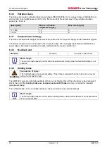
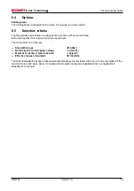
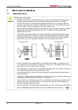
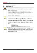
Summary of Contents for AM 3111

Page 1: ...Documentation Synchronous Servomotor AM3100 Version 1 4 Date 2012 04 20 ...

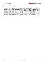
Page 2: ...ent Rated speed Rated supply voltage without brake with brake without brake with brake AM3111 030x 0 21 Nm 3 22 A 3000 min 1 24 V DC 0 026 Kgcm 2 0 034 Kgcm 2 0 40 Kg 0 48 Kg AM3112 040x 0 34 Nm 3 40 A 3500 min 1 48 V DC 0 046 Kgcm 2 0 054 Kgcm 2 0 54 Kg 0 62 Kg AM3121 020x 0 69 Nm 4 60 A 2000 min 1 48 V DC 0 15 Kgcm 2 0 20 Kgcm 2 0 85 Kg 1 03 Kg ...

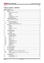
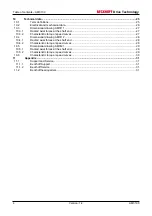
Page 3: ...Disposal 10 5 Product identification 11 5 1 Scope of supply 11 5 2 Nameplate 11 5 3 Type key 11 6 Technical description 12 6 1 Design of the motors 12 6 2 General technical data 12 6 3 Standard features 13 6 3 1 Style 13 6 3 2 Shaft end A side 13 6 3 3 Flange 13 6 3 4 Protection class 13 6 3 5 Insulation material class 13 6 3 6 Vibration class 14 6 3 7 Connection technology 14 6 3 8 Feedback unit ...

Page 4: ...tic torque speed curves 27 10 4 Dimensional drawing AM3112 28 10 4 1 Radial axial forces at the shaft end 28 10 4 2 Characteristic torque speed curves 28 10 5 Dimensional drawing AM3121 29 10 5 1 Radial axial forces at the shaft end 29 10 5 2 Characteristic torque speed curves 29 10 6 Characteristic torque speed curves 30 11 Appendix 31 11 1 Support and Service 31 11 1 1 Beckhoff Support 31 11 1 2...

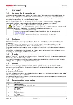
Page 5: ...ays have been fully checked for consistency with the performance data standards or other characteristics described If it should contain technical or editorial errors we reserve the right to make changes at any time and without notice No claims for the modification of products that have already been supplied may be made on the basis of the data diagrams and descriptions in this documentation 1 3 Br...

Page 6: ...trolled operation via digital servo motor ETHERCAT terminal EL7201 from Beckhoff WARNING Caution Risk of injury Electronic equipment is not fail safe The machine manufacturer is responsible for ensuring that the connected motors and the machine are brought into a safe state in the event of a fault in the drive system The servomotors from the AM3100 series are exclusively designed for installation ...

Page 7: ...E conformity of the complete machine or system 2 1 EC declaration of conformity We Beckhoff Automation GmbH Eiserstr 5 33415 Verl Germany hereby declare under our sole responsibility that the product range motor series AM3100 types AM3111 AM3112 and AM3121 complies with following relevant regulations EC Directive 2004 108 EC Electromagnetic compatibility EC Directive 2006 95 EC Electrical equipmen...

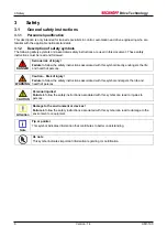
Page 8: ...afety instructions associated with this symbol directly endangers the life and health of persons WARNING Caution Risk of injury Failure to follow the safety instructions associated with this symbol endangers the life and health of persons CAUTION Personal injuries Failure to follow the safety instructions associated with this symbol can lead to injuries to persons Attention Damage to the environme...

Page 9: ...e Under unfavourable conditions arcing may occur resulting in injury and damage to contacts Disconnect the servomotor from the servo terminal and secure it against reconnection WARNING Serious risk of injury through hot surfaces The surface temperature may exceed 50 C resulting in a risk of burns Avoid touching the housing during or shortly after operation Leave the servomotor to cool down for at ...

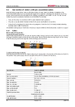
Page 10: ...ity 5 95 non condensing Max stacking height see table Packaging Storage time without limitation Store only in the manufacturer s original recyclable packaging 4 4 Maintenance Cleaning Maintenance and cleaning only by qualified personnel The ball bearings have a grease filling with a service life of 20 000 hours under normal operating conditions The bearings should be replaced after 20 000 hours of...

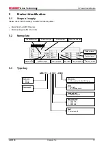
Page 11: ... Nn rpm Vdc Pn W Isol cl IP 5 3 Type key Servomotor type Serial number Date of manufacture Standstill current Standstill torque Nominal speed 1 Nominal speed 2 Protection class Rated voltage 2 Rated voltage 1 Insul class Rated output Flane size 1 40 mm 2 60 mm Rotor length 1 2 Nominal speed 2 2 000 min 1 4 3 500 min 1 5 5 500 min 1 Shaft 0 smooth shaft AM31 1 1 0 3 0 1 0000 Brake 0 No brake 1 24 V...

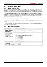
Page 12: ...f servo drives analyse the resolver position of the rotor and supply the motors with sine currents The motors are available with or without built in holding brake which is free from backlash The brake cannot be retrofitted The motors have a matt black coating similar to RAL 9005 The finish is not resistant against solvents e g trichlorethylene thinners or similar 6 2 General technical data Climate...

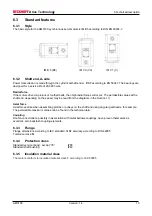
Page 13: ...shaft end depending on the speed may be read from the diagrams in the Section 10 Axial force Axial forces arise when assembling pinions or pulleys on the shaft and using angular gearheads for example The permissible maximum values can be found in the technical data Coupling Double coned collets possibly in association with metal bellows couplings have proven themselves as excellent zero backlash c...

Page 14: ...garding the cable materials can be found in Section 8 2 6 3 8 Feedback unit Standard Resolver Two pole hollow shaft Note Motor length The motor length depends on the built in feedback unit among other factors Retrofitting is not possible 6 3 9 Holding brake WARNING Serious risk of injury The holding brake is not personal safety If the brake is released then the rotor can be moved without a remanen...

Page 15: ...h units together form a speed or torque control loop The main selection criteria are Standstill torque M0 Nm Rated speed at rated supply voltage nn min 1 Moment of inertia of motor and load J kgcm Effective torque calculated Mrms Nm The static load and the dynamic load acceleration braking must be taken into account in the calculation of the required motors and servo drives Formulas and calculatio...

Page 16: ...he drive components where possible Blows or the use of force will lead to damage to the ball bearings and the shaft Wherever possible use only backlash free frictionally locking collets or couplings Ensure correct alignment of the couplings A displacement will cause unacceptable vibration and the destruction of the ball bearings and the coupling For toothed belts it is vital to observe the permiss...

Page 17: ...urther information regarding EMC shielding and earthing Earth the mounting plate and motor housing Further details of connection types can be found in Section 8 2 Route the power and control cables as separately as possible from one another separation 20 cm This will improve the immunity of the system to electromagnetic interference If a motor power cable is used which includes integral brake cont...

Page 18: ...ire additional information please contact our support 8 2 1 Cables Motor cable with signal line Connecting the plug connection Align the two plug connector 1 and 2 such that the white marking point 3 and the area 4 line up Push the two plug connectors together in the direction of the arrow Ensure that the black locking ring 5 can turn freely Press the two plug connectors together until the locking...

Page 19: ...EO Flexene polymer compound according to UL AWM CSA AWM Structure Shielding per pair Separator Polyester foil Colour code for signal pairs 1 pair 1st pair Black and red Electrical specifications Test conditions 20 C Test voltage power leads conductor conductor conductor shielding Test voltage signal leads conductor conductor conductor shielding Requirement 1 0 KV eff 5 min 0 5 KV eff 1min Operatin...

Page 20: ...ator Polyester strap Colour Ral 6018 green Signal leads 6 x 0 25 mm Conductor material blank copper Cl 5 DIN EN 60228 VDE 0295 IEC 60228 Insulation TEO Flexene polymer compound according to UL AWM CSA AWM Structure Pair wise twisted Separator Polyester foil Colour code for signal pairs 3 pairs 1st pair Brown and white 2nd pair Green and yellow 3rd pair Pink and gray Electrical specifications Test ...

Page 21: ...Drive Technology 8 Electrical installation AM3100 Version 1 4 21 8 2 2 EL7201 connection diagram for AM3100 motors with resolver Motor cable ZK4704 0411 2xxx Resolver cable ZK4724 0410 2xxx ...

Page 22: ...hield busbar 4 and press the shield busbar 4 into the receptacles of the shield busbar supports 1 Connect the cores 5 of the motor cable 6 and then fasten the copper sheathed end 7 of the motor cable 6 to the shield busbar 4 using the shield clamp 8 Tighten the screw 9 to the stop Secure the PE core 10 of the motor cable 6 under the PE clip 11 and securely tighten the screw 12 of the PE clip Move ...

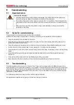
Page 23: ...he motor and the servo terminal Check that the earthing is correct Test the function of the holding brake if used apply 24 V the brake must be released Check whether the rotor of the motor revolves freely release the brake if necessary Listen out for grinding noises Check that all the required measures against accidental contact with live and moving parts have been carried out Carry out any furthe...

Page 24: ...ates Break in the shielding of the feedback cable Amplification to high Replace feedback cable Use motor default values Error message brake Short circuit in the supply voltage lead to the motor holding brake Faulty motor holding brake Remove the short circuit Replace motor Error message output stage fault Motor cable has short circuit or earth leakage Motor has short circuit or earth leakage Repla...

Page 25: ...rent of the servo drive used must be smaller Torque constant KTrms Nm A The torque constant defines how much torque in Nm is produced by the motor with 1A r m s current The relationship is M I x KT up to I 2 x I0 Voltage constant KErms mVmin The voltage constant defines the induced motor EMF as an effective sinusoidal value between two terminals per 1000 rpm Rotor moment of inertia J kgcm The cons...

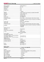
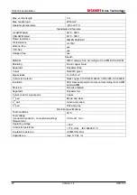
Page 26: ...resistance Ph PH R25 Ω 0 92 1 00 0 81 Winding inductance Ph Ph L mH 0 70 1 42 1 9 reference flange aluminium 250 mm x 250 mm x 6 mm Mechanical data Symbol Unit AM 3111 AM 3112 AM 3121 Rotor moment of inertia J kgcm 2 0 026 0 046 0 15 Pole number 8 8 8 Static friction torque MR Nm 0 0048 0 0096 0 0195 Thermal time constant tTH min 20 20 30 Weight standard G kg 0 40 0 54 0 85 Permitted radial force ...

Page 27: ...rsion 1 4 27 10 3 Dimensional drawing AM3111 10 3 1 Radial axial forces at the shaft end 10 3 2 Characteristic torque speed curves Characteristic torque speed curves see section 10 5 Resolver Motor type x without brake x1 with brake AM3111 91 122 ...

Page 28: ... 1 4 AM3100 10 4 Dimensional drawing AM3112 10 4 1 Radial axial forces at the shaft end 10 4 2 Characteristic torque speed curves Characteristic torque speed curves see section 10 5 Resolver Motor type x without brake x1 with brake AM3112 109 140 ...

Page 29: ...sion 1 4 29 10 5 Dimensional drawing AM3121 10 5 1 Radial axial forces at the shaft end 10 5 2 Characteristic torque speed curves Characteristic torque speed curves see section 10 5 Resolver Motor type x without brake x1 with brake AM3121 111 148 ...

Page 30: ...10 Technical data Drive Technology 30 Version 1 4 AM3100 10 6 Characteristic torque speed curves AM3111 AM3112 AM3121 ...

Page 31: ...ex automation systems extensive training program for Beckhoff system components Hotline 49 0 5246 963 157 Fax 49 0 5246 963 9157 e mail support beckhoff com 11 1 2 Beckhoff Service The Beckhoff Service Center supports you in all matters of after sales service local service repair service spare parts service Hotline 49 0 5246 963 460 Fax 49 0 5246 963 479 e mail service beckhoff com 11 2 Beckhoff h...

Reviews: