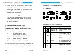
Release the frequency storage
Call up function “CS” using the
MDE
key. The following display appe-
ars:
left LC-Display
CS
right LC-Display
ON or OFF
Select the required setting using the
kHz
frequency selector switch and
store the selection by pressing the
STO
key.
OFF =
The storage of frequencies in the individual chan-
nels is not possible.
ON =
Storage of frequencies in the individual channels
is
possible (standard setting).
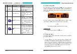
Erase stored frequencies
Call up function “dEL” using the
MDE
key. The following display appe-
ars:
left LC-Display
dEL
right LC-Display
CH channel number
Select the channel to be erased using the
kHz
frequency selector switch
(steps of 1) or
MHz
frequency selector switch (steps of 10) switch. The
stored frequency is erased by pressing the
STO
key. The channel
No. 1 cannot be erased.
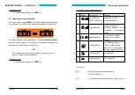
“ch” = free channel
“CH” = occupied channel (can be overwritten).
BECKER NR 3320 - ( ) / NR 3330 - ( )
Page 24
Issue 12/97
The microcontroller as well as its storage and peripheral components
are located on the processor board.
The GS receiver board is above the chassis board; and the VOR/LOC
receiver board and the VOR/LOC converter board are mounted below
the chassis board. Each of these three circuit boards is attached to the
chassis with four screws.
The VOR/LOC receiver is a triple-conversion superheterodyne receiver
and operates in the frequency range from 108.00 MHz to 117.95 MHz
with a channel separation of 50 kHz. The injection signal for the mixer is
generated by a voltage-controlled oscillator (VCO). The VCO is control-
led by digital frequency synthesizer which is mounted on the chassis
board. Digital frequency synthesis and storage are microproces-
sor-controlled.
The VOR/LOC conversion takes place on the VOR/LOC converter
board. The converted signals can then be read off the VOR/LOC pointer
of the connected VOR/ILS indicator.
The VOR/LOC converter board is omitted in the NR 3320 - (02) and
NR 3330 - (02) type. This type supplies only the NAV composite signal
to the VOR/LOC evaluation (for indicators with integrated VOR/LOC
evaluation).
The GS receiver is designed as a single-conversion superheterodyne
receiver and operates in the frequency range between 329.15 MHz and
335.00 MHz with a channel separation of 150 kHz. The injection fre-
quency for the receiver is generated by a voltage-controlled oscillator
(VCO). The VCO is controlled by a digital frequency synthesizer which
is mounted on the chassis board. The digital frequency synthesizer ope-
rates in conjunction with the microcontroller of the NAV receiver. The
converted GS signals can be read off the GS pointer of the connected
indicator.
Operating Instructions
Issue 12/97
Page 9

