background image

Cleaning and maintenance 


50/60 


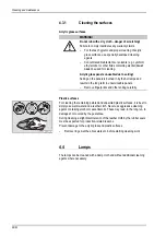
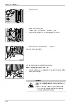
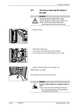
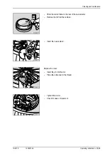
Remove the screw. 


Fold down the clamping strip. 


Use the suction cup to pull out the panel from the guide. 


Remove the panel to the side and carefully place it to one side. 


Remove the screws and then remove the lamp cover. 


Replacing lamps: see page 47. 


The assembly is the same process in reverse order. 


When assembling the device please note:


Insert the holding bar at the bottom with the hexagon in the recess of the 
holding device and align. 


 DANGER! 


Danger of crushing fingers when folding the clamping 
strip! 

Fingers can be crushed when folding the clamping strip. 


Do not hold fingers between the clamping strip and 
acrylic glass panel when folding. 


Summary of Contents for CVT 32

Page 1: ...BEAUTY ANGEL CVT 32 OPERATING INSTRUCTIONS...

Page 2: ......

Page 3: ...1020037 00 en 10 2018 Operating instructions Translation of the original operating instructions BEAUTY ANGEL CVT 32...

Page 4: ...licht de DANGER Failure to observe these instructions can result in serious injury and death can result in damage to the device and the environment Read these instructions carefully before putting th...

Page 5: ...training 12 1 5 3 Scope of delivery 12 1 5 4 Transport assembly and setup 12 1 5 5 Commissioning 15 1 5 6 Operation and maintenance 15 1 5 7 Decommissioning 16 1 5 8 Storage 16 1 5 9 Disposal 16 1 5 1...

Page 6: ...4 4 Lamps 42 4 5 Cleaning plan 43 4 6 Maintenance 44 4 7 Maintenance plan 45 4 8 Instructions for replacing the lamps 47 4 8 1 Beauty Light lamps 48 4 8 2 Makrolon tubes 49 4 9 Cleaning or replacing t...

Page 7: ...operation of the device as well as compliance with the maintenance intervals User A person who uses the device at a commercial location Personnel People who are responsible for the operation cleaning...

Page 8: ...ates the existence of a direct danger to body and life DANGER Type and source of hazard This safety notice warns of dangers to body and life which are caused by electricity WARNING Type and source of...

Page 9: ...lamps or their equivalent The usage times given in these operating instructions are valid only for the specified lamp set Any other use shall be considered improper The manufacturer cannot be held lia...

Page 10: ...cabin when using the device this especially applies to children 1 4 Device specific safety instructions 1 4 1 Prohibited usage beauty device NOTE Extending the specified application times cannot plac...

Page 11: ...jewellery including piercings prior to the application Remove cosmetics before using the device A light application is not damaging to the eyes if they are closed If the light intensity is experience...

Page 12: ...uterine devices contraceptive coils metal pins screws or plates are also only to use the device after consultation with their doctor Side effects The use of the vibration plate may lead to the followi...

Page 13: ...nt Comply with the application times Observe the safety instructions NOTE The application times are only valid for the lamp set speci fied on the sticker Skin type II Skin type II Skin type III Skin t...

Page 14: ...tended use and Foreseeable misuse safety instructions in the Operation chapter operating instructions cleaning and maintenance instructions Please make the instructions and additional information from...

Page 15: ...ined and author ized personnel Information regarding the disassembly and assembly of the device is availa ble in the separate assembly instructions These assembly instructions are intended solely for...

Page 16: ...or make any unauthorized chang es to the device The manufacturer shall bear no liability for damage or injuries resulting from such actions Observe the ventilation system data Do not set up and operat...

Page 17: ...power supply company This can for example interfere with the function of night storage heaters If faults occur due to the operation of the devices then the operator is re sponsible for the installati...

Page 18: ...al of lamps and batteries Your local sales agency will be happy to assist you with the disposal of lamps and batteries Report the number of lamps and batteries to your local agency by tele phone or in...

Page 19: ...oper ator towards the organisation responsible for issuing the commercial perfor mance rights For the public use of MP3 music files the same legislation applies as for all other music sources As a stu...

Page 20: ...difications The device has been constructed in accordance with the current state of the art and the applicable safety regulations The illustrations and specifications in these operation instructions a...

Page 21: ...t components are attached to the device The signs shown below are examples Ensure that the warning signs are always clearly recognisable and legible Any missing warn ing signs or stickers must be repl...

Page 22: ...Safety instructions and warnings 20 60 2 Serial number The serial number is located at the bottom left of the pillar 3 Maintenance instruction sticker 800701...

Page 23: ...Safety instructions and warnings 10 2018 1020037 00 Operating instructions 21 60 4 Connection sticker 1009050 The sticker is located behind the trim...

Page 24: ...t grease 1014572 The sticker is located behind the trim 6 EU warning sticker 1008607 This sticker also includes the language form 1504231 see Technical Doc umentation folder 7 No export USA Canada st...

Page 25: ...Safety instructions and warnings 10 2018 1020037 00 Operating instructions 23 60 8 Lamp set sticker The precise details of the required lamps are available in the separate appendix...

Page 26: ...uired This does not affect the rights of the customer under the existing warranty with regard to any claims that the customer might have in accordance with the contract of purchase 1 8 Warranty and li...

Page 27: ...els Protective goggles Technical documentation 2 1 1 Optional AROMA Central air outlet system 2 2 Equipment Device equipment varies depending on the model In this description all standard and optional...

Page 28: ...ating panel 4 Holding bars 5 Headphone connection jack plug 6 3 mm 6 AUX connection jack plug 3 5 mm 7 Fan body cooling 8 Loudspeakers 9 Beauty Light lamps 10 Clamping strips acrylic glass panels 11 I...

Page 29: ...fer in the metabolic system A pleasant side effect is an improved feel ing of general wellness and relaxation Over the medium and long term the skin complexion improves as a result of greater moisture...

Page 30: ...es the absorption and effect of cosmetic products 3 Refines the pores and improves the complexion 4 Provides the skin with a more lus trous and healthy appearance 5 Increases the resistance to environ...

Page 31: ...y Vibration supports muscular development stimu lates fat loss and improves mobility and physical coordination The improved microcirculation of the blood stimulates the metabolism and an improved feel...

Page 32: ...cillating fre quency Fitness programme for newcomers Medium oscillating frequency Fitness programme for advanced cus tomers High oscillating fre quency Improving the skin texture and guard ing against...

Page 33: ...time is only valid for the lamp set specified in the operating instructions Please observe the safety instructions and warnings in chapter 1 Procedure to be followed before during and after an applic...

Page 34: ...per week PROTECT Light 20 min Intensive 20 min VITALIZE Light 20 min Intensive 20 min RENEW Light 20 min Intensive 20 min Number Number Number Number Number Number 1st week 2 2 2 2 2 2 2nd week 2 2 2...

Page 35: ...tion tips Beauty device Stand up straight during the application and in the centre of the device WARNING Holding bars break when exposed to severe strain The holding bars can be broken off if they are...

Page 36: ...if an application time of less than 10 minutes has been entered A one minute long cooling down phase will start immediately example 7 minute application time 7 minute vibration programme 1 minute coo...

Page 37: ...s 35 60 3 4 Operating overview 1 START STOP button 2 Down navigation arrow button 3 Minus button 4 Display Functions 5 Vibra Shape diode 6 Body cooling pictogram 7 Volume pictogram 8 Audio system pict...

Page 38: ...ilable Change setting The diodes of the available functions and the navigation ring are illuminated in default mode after starting up the device After selecting a function the re spective diodes and t...

Page 39: ...cooling levels 1 5 Switch off cooling Switch on cooling The diodes next to the symbol illuminate according to the level set and 1 only the diode at the bottom illuminates 2 and 3 the diodes in the mi...

Page 40: ...Operation 38 60 3 6 Start Close the entrance Press the START STOP button Upon starting the following functions are activated UV high pressure lamps lamps Body cooling Audio system AROMA optional...

Page 41: ...the documentation from the manufacturer of the MP3 player or smartphone Connecting Insert the AUX cable stereo jack plug in the audio system Plug the AUX cable into the MP3 player or smartphone Select...

Page 42: ...undertaken by appropriately trained specialists If work is to be performed on the devices they must be deenergized That means that all live cables must be switched off Switching off the device alone i...

Page 43: ...More detailed information regarding the error description and solutions is available in Error Codes order no 1019969 4 3 Cleaning DANGER Infections can be spread by skin contact All objects device pa...

Page 44: ...lts in the long term in unserviceable panels Remove fingerprints and other soiling carefully Plastic surfaces For cleaning the remaining painted and unpainted plastic surfaces it is best to simply use...

Page 45: ...tic X Cleaning and disinfection 41 3 Control panel X Cleaning and disinfection 41 4 Holding bars X Cleaning and disinfection 41 Protective goggles X Cleaning and disinfection 41 AUX cable X Cleaning a...

Page 46: ...utely essential The current operating hours of maintenance parts can be called up in service mode see Presettings order no 1019970 We point out that the device must be subjected to regular inspections...

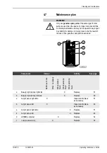
Page 47: ...of the use of non genuine spare parts is excluded Component Interval Activity See page Before each use When necessary 300 operating hours 1000 operating hours 3000 operating hours a Beauty Light lamp...

Page 48: ...een authorized trained and qualified by the manufac turer The correctly carried out maintenance work must be entered and confirmed in checklist 1019858 The maintenance work must be carried out at the...

Page 49: ...en replacing lamps Before carrying out maintenance work wait until the device has cooled down sufficiently NOTICE Small quantities of mercury can escape if the lamp glass breaks Please comply with the...

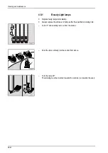
Page 50: ...ps immediately Always replace the entire set of lamps after the specified operating time Turn 90 and carefully remove from the socket Push the pins vertically into the socket from above Turn the lamp...

Page 51: ...h the new lamps Remove the makrolon tube from the old lamp Slide the makrolon tube onto the new lamp 4 9 Cleaning or replacing the lamps on the left WARNING Acrylic glass panels unusable due to soilin...

Page 52: ...e lamp cover Replacing lamps see page 47 The assembly is the same process in reverse order When assembling the device please note Insert the holding bar at the bottom with the hexagon in the recess of...

Page 53: ...ling carefully Remove the screw Fold down the clamping strip Use the suction cup to pull out the panel from the guide Remove the panel to the side and carefully place it to one side Remove the screws...

Page 54: ...e Replacing lamps see page 47 Makrolon tube see page 49 The assembly is the same process in reverse order When assembling the device please note Press in the sides of the lamp cover a little and inser...

Page 55: ...structions 53 60 Write the current date on the rear of the new canister Remove the lid from the canister Insert the new canister Replace the cover Insert the pin into the slot Place the cable next to...

Page 56: ...wer consumption rating with exhaust air 5400 W 5700 W Rated frequency 50 Hz Rated voltage 400 V 3 or 230 V 3 Rated fuses 3 x 16 A inactive 3 x 25 A inactive Connecting line H05VV F 5G 2 5 mm H05VV F 5...

Page 57: ...020037 00 Operating instructions 55 60 5 2 Dimensions B 1090 mm BK 2100 mm B1 700 mm BK1 375 mm B2 1350 mm TK 2400 mm B3 620 mm TK1 1000 mm T 1100 mm TK2 300 mm T1 700 mm T2 1100 mm H 2360 mm H1 2310...

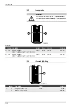
Page 58: ...ed Lamp set Number Description Length Power Control Order no a 16 Low pressure lamps BEAUTY ANGEL BEAUTY LIGHT 180 W C2 2 00 m 180 W 180 W 1011136 b 16 Low pressure lamps BEAUTY ANGEL BEAUTY LIGHT 180...

Page 59: ...0037 00 Operating instructions 57 60 5 5 Spare parts and accessories Number Description Order no 1 2 Acrylic glass panels 1506540 2 1 AROMA 5 ml WELLNESS 1009536 1 Protective goggles 84592 1 AUX cable...

Page 60: ...Appendix 6 1 JK timer controls The following coin modules time control systems can be utilized with the BEAUTY ANGEL CVT 32 series devices 04144 0 MCS III plus Order no 500000456 02508 1 Studiopilot O...

Page 61: ...Shape 9 Copyright 17 39 Cosmetics 9 31 Customer service 2 D Decommissioning 16 Definitions 5 Description 26 Device description 26 Device operating time 15 Dimensions 55 Directives 17 Disposal 16 E El...

Page 62: ...of injury 31 S Safety 13 Safety equipment 24 Safety instructions Device specific safety instructions 8 General safety instructions 12 Scope of delivery 12 25 Setup 12 Setup location 14 Side effects Vi...

Page 63: ......

Page 64: ...L CVT 32 JK INTERNATIONAL GMBH Koehlershohner Strasse 60 53578 Windhagen GERMANY Phone 49 0 2224 818 0 Fax 49 0 2224 818 500 Internet www beauty angel de www beauty angel eu E Mail info ergoline de GE...

Reviews: