


2
3
85235A
OPERATING INSTRUCTION
Type 125921020 _ Type 125921020SP _ Type 125943980 _ Type 125943980SP
In association with the installation and safety instructions for the
electric fencers
General Safety Instructions
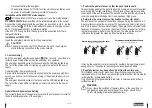
Switch off the pasture fencer before coming into contact with it!
Operating manual information
The operating manual has some important instructions on handling the energizer. All technical details in the manual
have been prepared and compiled with the greatest possible care. Even so, errors cannot be excluded. We wish to point
out that we cannot assume any guarantee, legal responsibility or any liability for consequences attributable to possible lack
of details. We would, at all times, welcome any notification of possible errors. Safe working depends on the indicated safety
and handling instructions being adhered to. Also to be adhered to are those local accident prevention provisions which are in
force where the energizer is used as well as the general safety requirements.
The operating manual is to be studied carefully before any work begins!
As an integral part of the overall product it is to be securely kept right next to the energizer and for ease of consultation by
the personnel.
Do hand over this manual should this product be sold or passed on to another party. For a better understanding of what is
involved, some of the diagrams in this manual may not be true-to-scale and may deviate slightly from the actual construction-
al design.
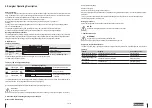
1. Description and Construction of the Product
The energizer transmits voltage pulses to a connected pasture fence.
Switching the energizer on and off is undertaken by a push switch
1
.
Caution!
Only the optional additional parts prescribed by the manu-
facturer are to be used.
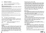
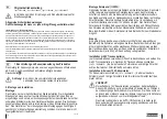
2. Installation
Installation:
Set up the energizer at a preferably moist location. The earthing rod supplied
must be driven as deeply as possible into the ground at a moist location and
connected by a high-voltage resistant connecting cable to the black earth-
ing terminal ( ) of the energizer. Connect the high-voltage resistant fence
cable to the red terminal with the lightning symbols ( ) . The energizer is only
protected against moisture if it is properly installed. Shield the energizer from
direct solar irradiation. Set the energizer up in a location where there is no
fire hazard.
Solar panel installation (<=20W):
Fasten the optional solar panel with the retaining plate at the energizer. The
energizer has an incorporated solar charge regulator (when the energizer
is switched on). Feed the cable into the housing through the cable inlet on
the back of the energizer and connect in the housing lid. Make sure that the
polarity is correct. Trouble-free solar operation is only possible in connection
with a 9 V battery or a 12 V rechargeable battery! Align the energizer with
the solar panel to face south. Use the lateral knurled nuts to determine and
fix the alignment and angle position of the solar panel.
Align the device with the solar panel to face south. Operation with the solar
panel means you cannot operate it with a mains adapter. The device has an
incorporated solar charge regulator (when the device is switched on).
Earthing:
Good earthing of the fence is extremely important for trouble-free operation
and optimum performance of the energizer; therefore it should be earthed at
a preferably moist and overgrown location.
If the ground is dry and the fence is long, an additional earth conductor with
intermediate earths (every 50 m) should be installed along the fence.
Installation with a 9V dry battery:
(use only alkaline batteries) Open the housing and insert the 9 volt dry
battery. Connect the energizer to the 9V dry battery (red + / black -), ensure
clean pole terminals and correct polarity. The energizer will not start if the
polarity is reversed.
Installation with a 12V rechargeable battery:
Connect the 12V rechargeable battery (red + / black -), ensure clean pole
terminals and correct polarity. The device will not start if the polarity is re-
versed.
CAUTION!
Only use rechargeable 12 V batteries; only charge rechargeable
batteries with ventilation in well-ventilated rooms. Disconnect the
rechargeable battery from the energizer during the charging process.
The rechargeable battery should be recharged before and after every
use as well as during longer periods of storage (every 2 months) and


