background image

SatDOCK-G 9555 Installation & User Manual

26

27

Preliminary Testing

Prepare the Iridium 9555 Handset

1.  Ensure that the 9555 Handset is running with the required  

compatible firmware which can be located at: 

www.beamcommunications.com/support/9555sdg

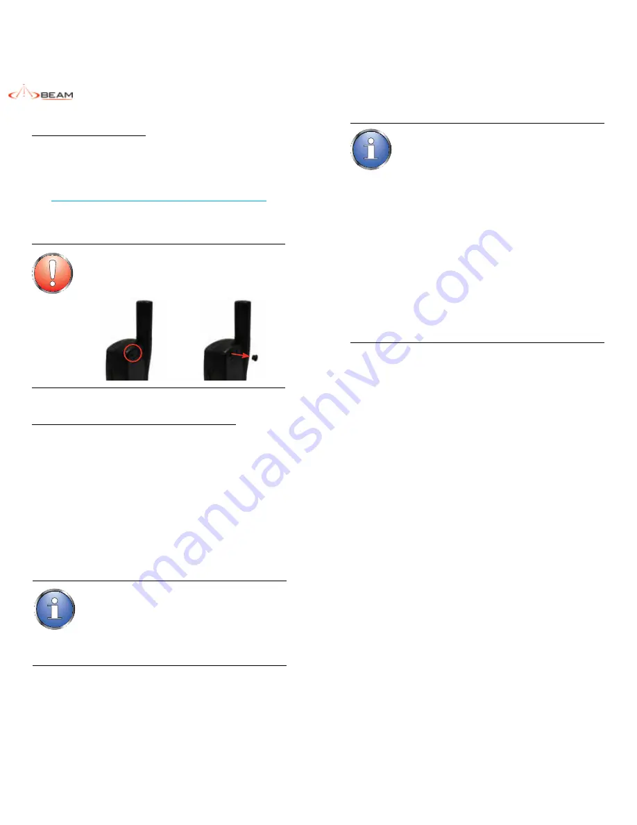
2.  Remove the rubber plug / bung / grommet from the rear of 

the 9555 Handset, to reveal the antenna socket hole.

Operation of the SatDOCK-G 9555

Starting Up

1.  Retract the antenna on the 9555 handset.
2.  Place the 9555 handset into the SatDOCK-G 9555 as per 

instructions “Docking & Undocking” on page 25.

3.  If using the 

YELLOW

 accessory input wire, switch the 

vehicle ignition to ACC or ON position, The SatDOCK-G 

9555 will automatically power up followed by a single 

beep. The 9555 handset will then start to initialise 

followed by a double (2) beep.

4.  Wait for the 9555 handset to register on the Iridium network.
5.  You are now ready to make and receive calls.

WARNING:


Ensure that the external antenna grommet at the rear 

of the 9555 handset is removed prior to inserting the 

handset into the SatDOCK-G 9555 cradle.

NOTE:

The 9555 handset can be removed whilst powered, 

however the handset will turn off automatically. 
If it is removed 

during

 a call, the 9555 will attempt to 

remain in call as long as antenna is extended and in sky 

view. The call may drop out during this transition, and the 

phone may turn off.

Charging the Iridium 9555 Handset

The SatDOCK-G 9555 provides charging power to the 9555 

handset via its base connector. Therefore, DO NOT plug another 

power supply into the 9555 side power port whilst it is docked in the 

cradle.
The 9555 battery is a lithium-ion cell which has a safety 

temperature range whilst  charging. This range is from 0 to 40 

degrees Celsius (32 to 104 degrees Fahrenheit).
Due to the increased heating effects on the 9555 handset 

whilst it is docked and being charged, it is ideal for the ambient 

temperature to be approximately 10 degrees below the 40 

degreeC upper limit for the handset to charge the battery whilst 

docked. If the battery temperature exceeds this limit, then the 

9555 may cease charging until the temperature is reduced. In 

some cases, the charging process may oscillate ON and OFF  

at the temperature limit. This could damage the Li-ion battery. 
To avoid the charging oscillation, the SatDOCK-G 9555 

employs  

a pulse powering mechanism to charge the 9555. Basically, 

charging power will be provided to the 9555 for a pre-defined 

duration (default 40 minutes) and then removed for another 

pre-defined duration (default 20 minutes). By turning off the 

charging for some time, it allows the 9555 battery to cool  

down and during the OFF period, if the temperature 

drops below a pre-defined level (default 28 degreeC), the 

SatDOCK-G 9555 will immediately turn on the charging power 

before the OFF timer expires. The charging ON, OFF and 

temperature level are configurable via the SDMS.

NOTE:

If the 9555 handset fails to connect with the cradle, the 

cradle will power cycle the 9555 twice when it is docked 

and after that, it will power down the 9555 and put it into a 

one-minute charge mode with the Ring/Mute LED flashing 

RED


and 

GREEN

.

After the one minute, the cradle will try again to connect 

with the 9555. If it still fails, the cradle will follow the 

above sequence however for a 10-minute duration.

One common cause for connection failure is a flat 9555 

battery which prevents the 9555 from being turned on in 

the cradle. The one-minute and ten-minute charge cycle 

will ‘resurrect’ the battery and once the 9555 is connected 

with the cradle, charging will resume on the 9555.
If the 9555 handset is removed from the cradle during 

the charging process, then reinserted, the startup 

process will restart from the beginning.
Please be patient during this startup sequence. Ringer 

/ Mute LED will flash 

RED


and 

GREEN

 during above 

charging process.

Summary of Contents for iridium SatDOCK-G 9555

Page 1: ...iridium SatDOCK G 9555 with built in GPS Installation User Manual Suitable for the Iridium 9555 Portable Satellite Telephone Beam Communications Pty Ltd ...

Page 2: ...ned subsidiary of World Reach Limited WRR listed on the Australian Stock Exchange is a world leader in design manufacture and distribution of specialized communications equipment for the Iridium Satellite Network BEAM s commitment to be at the forefront has continued to increase its share of the global satellite communications market Its premium distribution network spans the world Recognized as a...

Page 3: ...names are those of their respective owners RF Radio Frequencies AT AT tention command SMA SubMiniature version A co axial RF connection Package Contents Check that your SatDOCK G 9555 package contains 1 x SatDOCK G 9555 Docking Cradle 1 x Microphone 1 x Speaker 1 x DC Power Cable Lead 1 x RAM Bracket 3 x M4 Screw Set User Manual Quick Start Guide Optional Accessories The following optional accesso...

Page 4: ...ing 26 Prepare the Iridium 9555 Handset 26 Operation of the SatDOCK G 9555 26 Starting Up 26 Charging the Iridium 9555 Handset 27 Placing Voice Calls 28 Hands Free Phone Call Mobile Originating 28 Hands Free Phone Call Mobile Terminating 28 Bluetooth Phone Call Mobile Originating 29 Bluetooth Phone Call Mobile Terminating 29 Privacy Handset Use 30 Privacy Handset Phone Call Mobile Originating 30 P...

Page 5: ...he Iridium 9555 handset has an in built Iridium transceiver which is designed to be used with an external antenna This antenna transmits RF energy The Iridium antenna fitted via an extension coaxial cable to the cradle must be located more than 0 3 meters 1 foot from human body person when in operation International agencies have set standards and recommendations for the protection of public expos...

Page 6: ...tion cannot be guaranteed at all times or under all conditions Therefore you should never rely solely upon any wireless device for essential communications for example emergency calls Persons with pacemakers Should ALWAYS keep the phone more than six inches from their pacemaker when phone is turned ON Should turn the phone OFF immediately if you have any reason to suspect interference is taking pl...

Page 7: ...used in a vehicle enabling quality hands free calls with echo cancellation and noise reduction support SatDOCK G 9555 also has an in built Bluetooth module for voice and data connectivity Equipped with internal GPS the SatDOCK G 9555 provides an intelligent tracking and alert reporting system that can be easily configured to support periodic polling or emergency alert reporting Tracking Alert Moni...

Page 8: ...mponent being mounted to prevent the component from loosening over time Mount all components securely to prevent shifting that could cause injury or could interfere with safe vehicle operation Always use the supplied mounting hardware Leave space around the units to allow cooling and ensure there are adequate clearance for cables Ensure the units can be easily removed Routing Cables for vehicle in...

Page 9: ... resistance connections are present between the battery negative terminal the vehicle chassis and the engine block All wire connections should be clean and tight At 13 6 volts the SatDOCK G 9555 cradle draws a maximum of 1 amp current Please ensure that the vehicle s battery and alternator have sufficient current capacity to deliver at least 1 amp more than the maximum current that may be required...

Page 10: ... connector on the antenna cable coming from the rear of the SatDOCK G 9555 2b GPS Antenna Connection Optional The GPS connection is optional if the tracking function is required If connected and tracking is enabled position or location information will be shown on your tracking messages and alert messages The GPS connection supports an active GPS antenna compatible with powering from a 3 3V source...

Page 11: ...ns will OPEN activate the loop when pressed To properly register the alarm state the loop needs to be OPEN for at least 2 seconds ie holding down the button for 2 seconds activates the alarm NOTE The antenna should only be connected and disconnected to the GPS receiver when the SatDOCK G 9555 is not powered Connecting the antenna after power up can result in prolonged acquisition time 5 Connect Pr...

Page 12: ... The Intelligent handset allows the user to make calls or send receive SMS without having access to the 9555 handset The Intelligent handset can be installed up to 30 meters using a certified Beam extension cable away from the SatDOCK G cradle The intelligent handset is enabled when it is removed from the cup However if both the intelligent and privacy handsets are enabled the privacy handset alwa...

Page 13: ...GPS antenna and setup of the tracking and or alerting messages Please refer to the SDMS software to enable and configure Tracking Alert SatDOCK G 9555 Usage Docking undocking your 9555 handset To dock the 9555 handset place the base of the 9555 handset into the seat of the SatDOCK G 9555 ensuring that the pins on the bottom of the 9555 handset line up with that on the seat of the SatDOCK G 9555 cr...

Page 14: ... it is docked and being charged it is ideal for the ambient temperature to be approximately 10 degrees below the 40 degreeC upper limit for the handset to charge the battery whilst docked If the battery temperature exceeds this limit then the 9555 may cease charging until the temperature is reduced In some cases the charging process may oscillate ON and OFF at the temperature limit This could dama...

Page 15: ... options A and B from Hands free Phone Call Mobile Originating section are also applicable NOTE Country codes are not required if Call Processing is enabled in the SDMS Bluetooth Phone Call Mobile Originating A Bluetooth call can be started by using the 9555 keypad 1 Ensure that the Bluetooth audio headset is connected with the SatDOCK G 9555 i e the Bluetooth LED is turned on in BLUE half intensi...

Page 16: ...ont of the SatDOCK G 9555 B During call you may transfer the call to the optional Bluetooth audio headset if connected by a single short press of the Bluetooth button on the cradle This automatically directs the call audio to the Bluetooth device The Bluetooth LED will start slow flashing in BLUE to indicate the Bluetooth device is in use To return the audio back to the hands free mode perform ano...

Page 17: ...cking Position In order to send a tracking message the following condition must be fulfilled 1 The GPS receiver has acquired enough satellite signals and navigational data to calculate a positional solution fix 2 The 9555 handset is registered with the Iridium network 3 Tracking is configured and enabled via the SDMS The Track LED will stay off if the Tracking function is disabled It will turn sol...

Page 18: ... answer mode Turn off the auto answer mode LED turns solid GREEN and two tone beep LED goes OFF and single beep LOCATION BUTTON MODE ACTION LED SOUND Single Press No beep sound When Bluetooth is OFF Bluetooth is turned ON LED Starts fast flashing in BLUE when searching BT device and turns solid BLUE when connected with the BT device BT Device Used in Call Transfer the call to the HF mode or privac...

Page 19: ... then flash in RED when the alert message is sent Track LED will finally flash in ORANGE when the alert is acknowledged GREEN RED ORANGE ON Auto answer Enabled Outgoing audio is muted N A FLASHING N A 9555 Frame Sync not ready Privacy DPL handset in use or 9555 in earpiece mode during calls ALTERNATING Charging mode due to the communications failure with a docked 9555 N A GREEN RED ORANGE ON Alert...

Page 20: ...CK G 9555 as shown below Mini USB Data Port To connect a PC laptop to the SatDOCK G 9555 bottom mini USB port you will require a mini USB B to USB A data cable This cable is included in your original 9555 package TIP Learn more about Data Services available at www beamcommunications com NOTE When the 9555 is docked in the SatDOCK G 9555 cradle DO NOT use the USB port on the side of the 9555 Please...

Page 21: ...he following AT commands are affected AT COMMAND CRADLE DEFAULT STATUS LIMITATION AT IPR 6 0 Auto baud is permanently disabled with the default baud rate set to 19200 ATEn 1 Echo is on permanently enabled ATVn 0 Numerical responses only AT Cn 0 DCD is forced on at all times ATQ1 1 ISU responses are not sent to the DTE AT F0 Blocked AT W1 Blocked AT Yn Blocked Setting the Baud Rate If you wish to a...

Page 22: ... OK to redial the number automatically Assuring Quality of Iridium Service Iridium is committed to providing subscribers around the world with consistent reliable quality voice and data access all day every day The Iridium satellite system is monitored for call performance from numerous locations 24 hours a day 7 days a week in order to achieve this There are conditions that can compromise the qua...

Page 23: ...ctor on the cable loom for speaker and one vertical 2 pin Microfit connector for microphone Privacy Handset Line In Out 4 pole 3 5mm audio jack at the bottom of the SatDOCK cradle Data Port USB USB Mini B 5 pin female USB Slave USB 2 0 compliant CDC Serial profile Alarm Alert Loop 1 input 1 output Alarm Mode Normally Closed Loop IN to OUT Up to 45m cable run multiple buttons Power Cable 4 way Micr...

Page 24: ...Range 0 C to 40 C Operating Humidity Range 85 RH non condensing Storage Temperature 30C to 70C Weight Cradle 0 32kg 0 7 lbs Packed 1 3kg 2 86 lbs Atmospheric Protection Conformal Coating to Circuit Board Assy EMC Compliance CE IEC60945 2002 Section 9 10 2004 104 EC Automotive EMC directive RoHS Full compliant RoHS Directive EU 2002 95 EC All 6 substances WEEE For EU countries this product must be ...

Page 25: ...there are no damaged pins on this connector Re dock the 9555 into the SatDOCK Q5 The 9555 handset is inserted into the SatDOCK The battery indicator on the 9555 handset does not show that the battery is being charged A There are a number of reasons which could stop the 9555 battery charging When the 9555 handset is inserted into the SatDOCK please wait for about 100 seconds for the charging to sta...

Page 26: ... the date of shipment by BEAM Communications to the Customer BEAM Communications will repair or replace at our option any defective product provided that our analysis and or inspection discloses that such defects developed under normal and proper use 4 This warranty does not extend to goods subjected to liquid or particulate ingress extreme humidity misuse neglect accident or improper installation...

Page 27: ...WEB www beamcommunications com EMAIL info beamcommunications com PHONE 61 3 8588 4500 FAX 61 3 9560 9055 AFRICA ASIA AUSTRALIA EUROPE MIDDLEEAST NORTHAMERICA SOUTHAMERICA ...

Reviews: