


Remove the discharge
fi
lter assembly by
unscrewing the nut (134) and removing the lock
washer (132).
Carefully slide the assembly out of the exhaust
box. Stand the
fi
lter assembly up on a clean
fl
at
surface. To access the individual
fi
lters, unscrew
the two cylinder cover screws (126), remove the
two lock washers (128) and remove the exhaust
fi
lter grip plate (115).
Remove the exhaust
fi
lters (120) and O-rings
(121). Remove the
fi
lter support (118) and
O-rings (119).
Replace the support and O-rings with new ones.
Make sure that the O-rings are
fi
tted securely
and that the
fi
lter elements (120)
fi
t securely into
the depressions on the
fi
lter support (118). The
indicating arrow on each
fi
lter element must be
pointing upward toward the top of the exhaust
box after the assembly has been installed.
Carefully position the
fi
lter support tube (133)
between the exhaust
fi
lter grip (115) and the
fi
lter support without displacing the
fi
lters from
their seated position in the
fi
lter support. Install
the two lock washers (128) and two screws (126).
Insert the support and
fi
lter assembly into the
exhaust box using the stud (131) as a guide. The
stud should slide through the hole in the support
(133). Secure the assembly with the lock washer
(132) and hexagon nut (134).
Reinstall the sheet metal plate (136) and the
ba
ffl
e strainer (130) into the guide track of the
exhaust box. Press to the bottom of the exhaust
box and make sure that the ba
ffl
e strainer
touches all sides of the exhaust box. Insert the
distance sleeve (137) into the two grooves. This
holds the sheet metal plate and ba
ffl
e strainer
in place.
Inspect the exhaust box and cover gasket (141)
for damage and replace if damaged. With the
For 5 Hp (RA0155)
To replace the exhaust
fi
lters, unscrew the
screws (142) and lock washers (143) from the
exhaust cover plate (140). Remove cover plate
and gasket (141).
Use a slotted head screw driver to loosen the
exhaust
fi
lter retaining spring (125), then rotate
and remove the spring. Pull the
fi
lter cartridge
(120) out of the exhaust box.
Reinstall the
fi
lter elements. Make sure the open
end of the element is properly seated down in
its recess in the exhaust box with the O-ring
(121) correctly positioned. The indicating arrow
on each
fi
lter element must be pointing upward
toward the top of the exhaust box after the
assembly has been installed.
Retain the
fi
lter with the spring clip (125), tighten
the tension screw until the
fi
lter is secure.
Place the exhaust port gasket (141) and cover
(140) in position on the exhaust box and retain
with the cap screws (142) and lock washers (143).
For 7.5 Hp and 10 Hp
To replace the exhaust
fi
lters, unscrew the screws
(142) and washers (143) from the exhaust cover
plate (140). Remove cover plate and gasket (141).
Remove the distance pin (137), the ba
ffl
e strainer
(130) and the sheet metal plate (136).
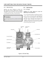
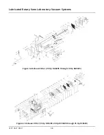
NOTE:
Refer to Figure 6.4 for numbers referenced
below in parenthesis.
NOTE:
Refer to Figure 6.3 for numbers referenced
below in parenthesis.
Lubricated Rotary Vane Laboratory Vacuum Systems
4107 9021 88.01
6-5


