


15
Part No. 6-847684-00 Rev. D01
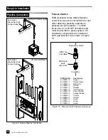
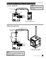
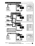
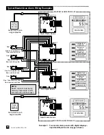
Wiring Schematic 2: Sensor Module to Digital Display Module
Digital Display Module
Digital Display Module
Remote sensor mounting box
(remote from alarm panel)
Local sensor
(inside alarm panel back box)
2-pin polarized connector
2-pin polarized connector
ribbon to
adjacent
module
LOCAL SENSOR
REMOTE SENSOR
ribbon to
adjacent
module
*
Sensor pigtail
Sensor pigtail
(provided)
Wire nuts
Field wiring
(by others)
*
NOTE:
Sensor pigtails for local sensors
are factory connected to digital dis-
play module.
Pin 5 - red (+)
Pin 6 - black (-)
Pin 5 (+)
Pin 6 (-)
NOTE:
Field wiring cable shields must be grounded at
only one end, inside alarm panel back box. Refer
to page 31 for details.


