Bdcom S2210PB Hardware Installation Manual Download Page 3

S2210PB Hardware Installation Manual

- 1 -

Chapter 1

S2210PB Switch Overview

The document describes the characteristics and parameters of S2210PB and gives an

overview of S2210PB.

1.1 Standard Configuration

S2210PB switch has three parts: 8 IEEE802.3af/at 100M Ethernet TX ports, 2 gigabit

Ethernet SFP ports and 1 Console port. See the following table:

Table 1-1 Attributes of necessary ports

Port

Features

100M PoE ports

TX port: a rate of 10/100M auto-adaptation,
cable

MDI/MDIX

auto-identification,

UTP(RJ45) port

gigabit Ethernet optical ports

Optical port: 100/1000M SFP port, with LINK/
ACT indicators

Console port

A rate of 9600bps, RJ45 interface

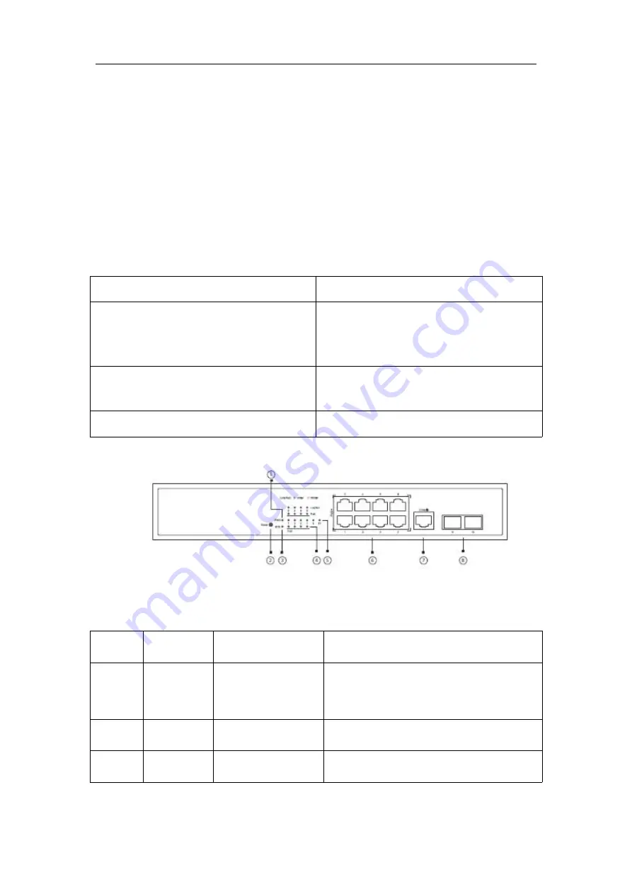
Figure 1-1 Front template of the S2210PB switch

Table 1-2 Parts at the front template of the S2210PB switch

No.

Abbrev.

Name

Remarks

1

PWR

power indicator

If the switch is powered on, the indicator is

on.

2

RESET

RESET

Resume to the default setting.

3

SYS

System indicator

If the indicator is always on, the system is

Summary of Contents for S2210PB

Page 1: ...S2210PB Hardware Installation Manual ...

Page 2: ...Power Requirements 7 2 4 Installation Tools and Device 7 Chapter 3 Installing the S2210PB Switch 8 3 1 Installation Procedures of S2210PB 8 3 2 Installing the Chassis of S2210PB 8 3 2 1 Installing the Chassis on the Desk 8 3 2 2 Installing the Chassis on the Cabinet 8 3 3 Connecting the Port 9 3 3 1 Connecting the Console Port 9 3 3 2 Connecting the SFP Ports 11 3 3 3 Connecting 100M Ethernet TX P...

Page 3: ...sary ports Port Features 100M PoE ports TX port a rate of 10 100M auto adaptation cable MDI MDIX auto identification UTP RJ45 port gigabit Ethernet optical ports Optical port 100 1000M SFP port with LINK ACT indicators Console port A rate of 9600bps RJ45 interface Figure 1 1 Front template of the S2210PB switch Table 1 2 Parts at the front template of the S2210PB switch No Abbrev Name Remarks 1 PW...

Page 4: ...000M is transmitted No indicator is on no signal is transmitted 6 8 RJ45 interfaces Realizes the PoE function and forwards 10 100M Ethernet electrical signals 7 Console Console Manages the switch locally 8 2 SFP ports Realizes the forward of gigabit Ethernet optical signals Besides S2210PB provides with a grounding column a power socket and a silent fan Figure 1 2 Back template of the S2210PB swit...

Page 5: ...uting protocol standard RFC 1058 RIP RFC 1723 RIP v2 Network management standard RFC 1157 SNMP v1 v2 RFC 1213 MIB II RFC 1757 RMON 1 2 3 9 Hardware features Memory Flash Memory 16M Bytes DDR3 128Mbytes Standard configuration 2 Gigabit Ethernet SFP ports 1 Console port 8 100M Ethernet TX ports Dimensions W H D mm 280 180 44 Operating temperature humidity 0 to 40 10 90 non condensing Storage tempera...

Page 6: ...S2210PB Hardware Installation Manual 4 1 3 ROHS Description ...

Page 7: ...roducts to our company for collective processing 2 2 Safety Advice 2 2 1 Safety Principles Keep dustless and clean during or after the installation Put the cover at the safe place Put tools at the right place where they are not easily falling down Put on relatively tight clothes fasten the tie or scarf well and roll up the sleeve avoiding stumbling the chassis Put on the protective glasses if the ...

Page 8: ...s power B Alarm C Take proper measures to help persons who are hit by the disaster Artificial respiration is needed if necessary D Seek for medical help or judge the loss and seek for available help 2 2 4 Electrostatic Discharge Damage Prevention Electrostatic discharge may damage devices and circuits Improper treatment may cause the switch to malfunction completely or discontinuously Move or loca...

Page 9: ... installed at the bottom of the cabinet The clapboard separates exhaust gas and inflow air and boost the cool air to flow in the chassis The best location of the clapboard is decided by the air flow mode in the chassis which can be obtained through different location tests 2 3 4 Power Requirements Make sure that the power supply has nice grounding and the power at the input side of the switch is r...

Page 10: ...he operations according to the following procedure It can be described in the following two parts Installing the Chassis on the Desk Installing the Chassis on the Cabinet 3 2 1 Installing the Chassis on the Desk The S2210PB switch can be directly put on the smooth and safe desk Note Do not put things weighing 4 5 kg or over 4 5 kg on the top of the switch 3 2 2 Installing the Chassis on the Cabine...

Page 11: ...the console port to the serial port of PC through a console cable you can configure and monitor the switch of S2210PB by running a terminal emulation software such as super Windows terminal The cable is provided according to the host The communication parameters of the terminal serial port can be set to a rate of 9600bps eight data bits one stop bit no sum check bit and traffic control The RJ45 co...

Page 12: ... Because the console port of S2210PB bears no flow control you need to set Data flow control to none when using a superior terminal to manage S2210PB configurations or the single pass problem will arise from the superior terminal The cable is used to connect the console port of the S2210PB switch and the outside console terminal device One end of the cable is a 8 pin RJ45 plug and the other end is...

Page 13: ... to one indicator respectively which is used for indicating the port Link ACT state When the indicator is always on the link is normal when it flickers the data receives and forwards To use the optical port you need connect it to the SFP optical module and then to other Ethernet terminal devices through an optical fiber Figure 3 6 Connecting the SFP ports and other Ethernet terminals ...

Page 14: ...ing order of the pins in the UTP port is the same as the console port Figure 3 7 RJ 45 connector of the console port Because 8 10 100Base TX ports of S2210PB support the MDI MDIX auto identification of the cable S2210PB can adopt five classes of direct through cross network cables when it connects other Ethernet terminals Figure 3 6 Connecting Base T ports and other Ethernet terminal Table 3 3 Def...

Page 15: ...ve classes of direct through cross network cables can be used to connect other Ethernet devices 3 4 Checkup after Installation Before feeding power to start the switch perform the following checkups after the switch is installed If the switch is installed on the DIN rail check whether the installation is strong If the switch is installed on the desk check whether there is enough space for the swit...

Page 16: ...u need some tools which the standard configuration of S2210PB does not provide These tools are Crossed screwdriver Static armguard Perform the following steps to open the cover of the switch 1 Cut off the power of the switch 2 Plug out all cables connected the back of the switch 3 Take out the bolt from the chassis with the screwdriver Note The chassis comprises of two parts cover and bottom 4 Ope...

Page 17: ...ing the directions shown on the above mentioned figure install the cover and bottom of the frame box 2 Nail the bolt and screw it tightly with the screwdriver 3 Reinstall the switch on the DIN rail or on the desk 4 Reconnect all cables of the switch ...

Page 18: ...ther the air outlet and air inlet are clean and then do relative operations in section 2 3 Requirements for Common Locations If the switch cannot be started and the PWR indicator is off check the power 5 1 2 Faults Relative with Port Cable and Connection Do the following checkups to help remove the fault If the port of the switch cannot be linked check whether the cable is correctly connected and ...

Page 19: ...l contents of this manual and must not broadcast it in any manner Trademark claims Trademarks product names service names and company names which are written in this manual but do not belong to the company belong to their owners respectively Disclaimer of warranty provides no evident or hinted guarantee towards the contents of this manual In no event except for the company s breach of law shall th...

Reviews: