RX61H User’s Manual
73
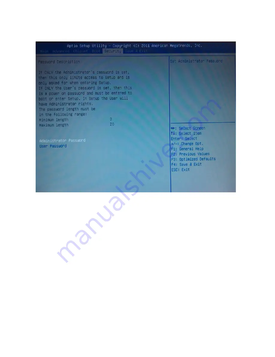
2.7 Security
Administrator Password
Set setup Administrator Password
User Password
Set User Password
Page 1: ...RX61H Intel H61 Micro ATX Motherboard mATX supports 2nd 3rd Generation Intel Core i7 i5 i3 Processors Sandy Bridge Ivy Bridge Processors User s Manual Ver 1 0...
Page 2: ...ng contact your local power company If the power supply is broken do not try to fix it by yourself Contact a qualified service technician or your retailer Operation safety Before installing the mother...
Page 3: ...ce complies with the requirements in Part 15 of the FCC rules Operation is subject to the following two conditions This device may not cause harmful interference This device must accept any interferen...
Page 4: ...ation Refer to the following sources for additional information and for product and software updates 1 Technical Support If a problem arises with your system and no solution can be obtained from the u...
Page 5: ...press the enclosed key Example Enter means that you must press the Enter or Return key Key1 Key2 Key3 If you must press two or more keys simultaneously the key names are linked with a plus sign Examp...
Page 6: ...r single board please make sure that the following materials have been shipped 1 x RX61H Micro ATX Main board 1 x DVD ROM contains OS device drivers 2 x SATA cables 1 x I O Shield 1 x Quick Installati...
Page 7: ...RX61H User s Manual RX61H User s Manual 7 Revision History Revision Revision History Date V 1 0 First release version 2012 08 31...
Page 8: ...ights 12 1 2 Before you Proceed 15 1 3 Motherboard Overview 16 1 4 Central Processing Unit CPU 19 1 5 System Memory 26 1 6 Expansion Card 30 1 7 Jumpers 33 1 8 Connectors 35 Chapter 2 BIOS Setup 44 2...
Page 9: ...B Display Intel HD Graphics 2000 3000 4000 DVMT Support up to 1 7GB Memory Audio Realtek ALC892 5 1 with Multiple Streaming HD Audio LAN Intel 82579LM Gigabit Ethernet controller Intel 82583V Gigabit...
Page 10: ...xpansion Slots 1 x PCI E x16 slot 2x PCIe x1 slot 1 x PCI Slots PCI 2 3 compliant DIO 8 Bit GPIO S3 S4 Yes TPM N A Wake up on LAN or Ring LAN PXE Smart Fan Control Yes Display Chipset Intel HD Graphic...
Page 11: ...or 1 x Front Audio connector 1 x Amplifier header 1 x Front panel header 1 x Printer port 1 x 8 Bit DIO connector 2 x LAN LED header 1 x AT ATX power jumper 1 x 24 pin ATX Power connector 1 x 4 pin AT...
Page 12: ...the most terrific computing experience from the present to the future Integrated 5 1 channel HD Audio CODEC delivering advanced multi channel audio and bringing you the experience of home theater qual...
Page 13: ...Extensions Intel AVX Intel AES New Instructions Integrated Display Interfaces Dual Independent Display Support DVI D Analog VGA Intel HD Graphics 4000 3000 2000 DirectX 10 1 Improved realism for DX 3...
Page 14: ...us 2 0 LPC Bus Supports SPI devices Hardware Monitor Fan control Voltage Temp Watchdog timer Power Management Dual Dynamic Power Management Separate power planes for cores and memory controller Advanc...
Page 15: ...bject such as the power supply case before handling components to avoid damaging them due to static electricity Hold components by the edges to avoid touching the ICs on them Whenever you uninstall an...
Page 16: ...ailure to do so can cause you physical injury and damage motherboard components 1 3 1 Placement Direction When installing the motherboard make sure that you place it into the chassis in the correct or...
Page 17: ...rboard Layout 1 3 4 Layout Content List Slots socket Label Function Note Page CPU1 LGA1155 CPU socket 19 DIMMA1 240 pin DDR3 DIMM Slot A1 26 DIMMB1 240 pin DDR3 DIMM Slot B1 26 PCIEX16 PCI e x16 Slot...
Page 18: ...Microphone Port 5 1 Channel Audio I O 3 jacks 35 1 3 5 Internal Connector Internal Connector Label Function Note Page FAN1 CPU Fan Connector 4 x 1 wafer pitch 2 54mm 36 FAN2 System Fan Connector 4 x...
Page 19: ...g or if you see any damage to the PnP cap socket pins motherboard components Supplier will shoulder the cost of repair only if the damage is shipment transit related Keep the cap after installing the...
Page 20: ...he load lever is on your left 2 Press the load lever with your thumb A then move it to the left B until it is released from the retention tab To prevent damage to the socket pins do not remove the PnP...
Page 21: ...socket then fit the socket alignment key into the CPU notch 5 Pull back the load lever then push the load lever A until it snaps into the retention tab The CPU fits in only one correct orientation DO...
Page 22: ...nd fan Your Intel Core i7 i5 i3 LGA1155 processor LGA1155 heatsink and fan assembly comes in a push pin design and requires no tool to install If you purchased a separate CPU heatsink and fan assembly...
Page 23: ...sembly in place 3 Connect the CPU fan cable to the connector on the motherboard labeled CPU_FAN FAN 1 CPU FAN Do not forget to connect the fan cables to the fan connectors Insufficient air flow inside...
Page 24: ...fan 1 Disconnect the CPU fan cable from the connector on the motherboard 2 Rotate each fastener counterclockwise 3 Pull up two fasteners at a time in a diagonal sequence to disengage the heatsink and...
Page 25: ...RX61H User s Manual RX61H User s Manual 25 5 Rotate each fastener clockwise to ensure correct orientation when reinstalling...
Page 26: ...ts 240 Pin DDR3 DIMM sockets Channel Socket Channel A DIMMA1 Channel B DIMMB1 1 5 2 Memory Configurations You may install 1 GB 2 GB 4 GB and 8 GB non ECC DDR3 DIMMs into the DIMM sockets using the mem...
Page 27: ...u obtain memory modules from the same vendor Refer to the memory Qualified Vendors List on the next page for details Due to CPU limitation DIMM modules with 128 Mb memory chips or double sided x16 mem...
Page 28: ...R DIMMs DO NOT install DDR2 DIMMs to the DDR3 DIMM socket Make sure to unplug the power supply before adding or removing DIMMs or other system components Failure to do so may cause severe damage to bo...
Page 29: ...Simultaneously press the retaining clips downward to unlock the DIMM 2 Remove the DIMM from the socket Support the DIMM lightly with your fingers when pressing the retaining clips The DIMM might get...
Page 30: ...posite the slot that you intend to use Keep the screw for later use 4 Align the card connector with the slot and press firmly until the card is completely seated on the slot 5 Secure the card to the c...
Page 31: ...ess x1 slots that complies with the PCI Express specifications The following figure shows an expansion card installed on the PCI Express x 1 slot 1 6 5 PCI slot This motherboard supports one PCI slot...
Page 32: ...RX61H User s Manual 32 RX61H User s Manual...
Page 33: ...e jumper cap from pins 1 2 default to pins 2 3 Keep the cap on pins 2 3 for about 5 10 seconds then move the cap back to pins 1 2 4 Re install the battery 5 Plug the power cord and turn ON the compute...
Page 34: ...RX61H User s Manual 34 RX61H User s Manual 1 7 2 AT ATX Power Mode Select PSON1 This jumper allows you to select ATX Mode or AT mode 1 7 3 COM1 COM2 RI 5V 12V Select JCOMPWR1 JCOMPWR2...
Page 35: ...w for the LAN port LED indications LAN port LED indications SPEED LED ACT LINK LED Status Description Status Description OFF 10Mbps connection OFF No link Green 100Mbps connection Orange Link Orange 1...
Page 36: ...onnect the fan cables to the fan connectors on the motherboard making sure that the black wire of each cable matches the ground pin of the connector Note FAN1 CPU Fan FAN2 System Fan FAN3 Chassis Fan...
Page 37: ...eset Button Pin 5 7 SYS_RST This 2 pin connector is for the chassis mounted reset button for system reboot without turning off the system power Power LED Pin 2 4 PWRLED This 2 pin connector is for the...
Page 38: ...Find the proper orientation and push down firmly until the connectors completely fit Use of a PSU with a higher power output is recommended when configuring a system with more power consuming devices...
Page 39: ...RX61H User s Manual RX61H User s Manual 39 1 8 5 Digital IO Connector JDIO1 This connector is for 8 bit General purpose I O function 1 8 6 LPT Port Connector LPT This connector is for print port...
Page 40: ...either HD Audio or legacy AC 97 optional audio standard Connect one end of the front panel audio I O module cable to this connector For motherboards with the optional HD Audio feature we recommend th...
Page 41: ...RX61H User s Manual RX61H User s Manual 41 1 8 9 Serial ATA Connector SATA1 SATA2 SATA3 SATA4 These connectors support SATA 2 0 and are for the Serial ATA signal cables for Serial ATA hard disk drives...
Page 42: ...to any of these connectors then install the module to a slot opening at the back of the system chassis These USB connectors comply with USB 2 0 specification that supports up to 480 Mbps connection sp...
Page 43: ...RX61H User s Manual RX61H User s Manual 43 This chapter tells how to change the system settings through the BIOS Setup menus Detailed descriptions of the BIOS parameters are also provided 2 BIOS SETUP...
Page 44: ...ram Press Del during the Power On Self Test POST to enter the Setup utility otherwise POST continues with its test routines If you wish to enter Setup after POST restart the system by pressing Ctrl Al...
Page 45: ...s field A sub menu contains additional options for a field parameter To display a sub menu move the highlight to the field and press Enter The sub menu appears Use the legend keys to enter values and...
Page 46: ...the following screen appears The BIOS menu screen displays the items that allow you to make changes to the system configuration To access the menu items press the up down right left arrow key on the k...
Page 47: ...items in this menu Use this menu for basic system configurations such as time date etc BIOS Information Displays the BIOS version CPU Information Displays the auto detected CPU information Memory Info...
Page 48: ...ipset configuration to go to the sub menu for that item You can display an Advanced BIOS Setup option by highlighting it using the Arrow keys All Advanced BIOS Setup options are described in this sect...
Page 49: ...ormation of PCI Bus Driver Version PCI 64bit Resources Handling Above 4G Decoding Disabled Enables or disables 64bit capable devices to be decoded in above 4G address space only if system supports 64b...
Page 50: ...only CPU Stop Clock S3 only Suspend to RAM S3 Video Repost Disabled Enable or disable S3 video repost Configuration options Disabled Enabled Resume On RTC Alarm Disabled Enable or disable system wake...
Page 51: ...e Processor Cores All Select the numbers of cores in each processor package Configuration options All 1 2 3 4 It depends on each CPU type Intel Virtualization Technology Disabled When enable a VMM can...
Page 52: ...ser s Manual 2 4 4 SATA Configuration SATA Controller s Enabled Enabled or disabled SATA device Configuration options Disabled Enabled SATA Mode Selection IDE Determines how SATA controller s operate...
Page 53: ...ers USB Device Display how many devices are connected Legacy USB Support Enabled Enables Legacy USB support AUTO option disables legacy support if no USB devices are connected DISABLE option will keep...
Page 54: ...RX61H User s Manual 54 RX61H User s Manual 2 4 6 Super IO Configuration System Super IO Chip Parameters Super IO Configuration Super IO Chip NCT6776F...
Page 55: ...Port Enable Enable or Disable Serial Port Configuration options Disabled Enabled Device Setting IO 3F8h IRQ 4 Change Setting Auto Select an optimal setting for Super IO device Configuration options A...
Page 56: ...Port Enable Enable or Disable Serial Port Configuration options Disabled Enabled Device Setting IO 2F8h IRQ 3 Change Setting Auto Select an optimal setting for Super IO device Configuration options A...
Page 57: ...sabled Enabled Device Setting IO 378h IRQ 7 Change Setting Auto Select an optimal setting for Super IO device Configuration options Auto IO 378h IRQ 7 IO 378h IRQ 5 6 7 9 10 11 12 IO 278h IRQ 5 6 7 9...
Page 58: ...ed watch dog timer function Configuration options Disabled Enabled GPIO Group Control Disabled Configure the digital GPIO pins Configuration options Disabled Enabled Configuration options Input Output...
Page 59: ...RX61H User s Manual RX61H User s Manual 59 2 4 7 1 Smart Fan Set smart fan function Smart Fan Function Enabled Enabled or disabled smart fan function Configuration options Disable Enabled...
Page 60: ...sable Enabled Chassis MIN FAN Speed 62 5 Set minimum chassis fan speed Configuration options 12 5 25 37 5 50 62 5 75 87 5 CPU Smart Fan Target Disabled Set CPU smart fan target temperature Configurati...
Page 61: ...12 5 25 37 5 50 62 5 75 87 5 2 4 8 Option Rom Policy Launch Storage OpROM policy Enabled Controls the execution of UEFI and Legacy storage OpROM Configuration options Disabled Enabled Other PCI device...
Page 62: ...isabled Enabled CPU C3 Report Enabled Enabled or disabled CPU C3 ACPI C2 report to OS Configuration options Disabled Enabled CPU C6 Report Enabled Enabled or disabled CPU C6 ACPI C3 report to OS Confi...
Page 63: ...RX61H User s Manual RX61H User s Manual 63 2 5 Chipset...
Page 64: ...RX61H User s Manual 64 RX61H User s Manual 2 8 1 PCH IO Configuration Display PCH Information...
Page 65: ...Express Configuration 2 8 1 1 1PCI Express Root Port 1 PCIe Speed Auto Select PCI Express port speed Configuration options Auto Gen1 Gen2 2 8 1 1 2PCI Express Root Port 2 PCIe Speed Auto Select PCI E...
Page 66: ...ontroller must always be enabled Configuration options Disabled Enabled EHCI1 Enabled Control the USB EHCI USB 2 0 functions One EHCI controller must always be enabled Configuration options Disabled E...
Page 67: ...ons Disabled Enabled Auto Amplifer GAIN db 15 3db Select Amplifier GAIN value Configuration options 15 3db 21 2db 27 2db 31 8db LAN1 Controller Enabled Enable Disable LAN1 Controller Configuration opt...
Page 68: ...d Enabled LAN2 Option ROM Disabled Optional Enable Disable LAN2 boot option for legacy network devices Configuration options Disabled Enabled Restore AC Power Loss Power Off Specify what state to go t...
Page 69: ...ion options Auto Disabled Enabled DVMT Pre Allocated Mem 64M Select DVMT 5 0 pre allocated fixed graphics memory size used by internal graphics device Configuration options 32M 64M 96M 128M 160M 192M...
Page 70: ...EG0 ASPM Auto Control ASPM support for the PEG Device 1 Function 0 This has no effect if PEG is not the currently active device Configuration options Disabled Auto ASPM L0s ASPM L1 ASPM L0sL1 Enable P...
Page 71: ...RX61H User s Manual RX61H User s Manual 71 2 8 2 3 Memory Configuration Display Memory information...
Page 72: ...5 0xFFFF means indefinite waiting Bootup NumLock State On Select the keyboard NumLock state Configuration options On Off Customer Logo Disabled Show custom logo in POST screen Configuration options Di...
Page 73: ...RX61H User s Manual RX61H User s Manual 73 2 7 Security Administrator Password Set setup Administrator Password User Password Set User Password...
Page 74: ...anual 2 8 Save Exit Save changes and Exit Exit system setup after saving the changes Discard changes and Exit Exit system setup without saving the changes Load Optimized Defaults Restore the user defa...