BCM Advanced Research MX965Q User Manual Download Page 27


27

1.8


  Power Supply 

 
1.8.1


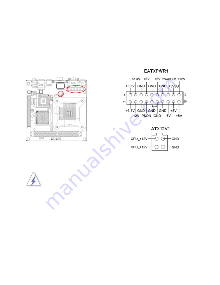
  ATX Power Connectors:    EATXPWR1 (20-pin), ATX12V1 (4-pin) 

These connectors are for ATX power supply plugs. The power supply plugs are designed to fit these 

connectors in only one orientation. Find the proper orientation and push down firmly until the 

connectors are completely fit.   


1.  For a fully configured system, we recommend that you use a power supply unit 

(PSU) that complies with ATX 12 V specification 2.0 (or later version) and provides a 

minimum power of 400W.   

2.  Do not forget to connect the 4-pin ATX12V1 power plug; otherwise, the system will 

not boot.   

3.  Use of a PSU with a higher power output is recommended when configuring a 

system with more power-consuming devices. The system may become unstable or 

may not boot if the power is inadequate.   


Summary of Contents for MX965Q

Page 1: ...1 Mini iTX MX965Q Intel 65nm Core 2 Duo Pentium Dual core Pentium 4 Pentium D Celeron 440 w 1066 800 533MHz FSB User s Manual Rev 1 00 Nov 2008...

Page 2: ...N ACCORDANCE WITH THE INSTRUCTION MANUAL MAY CAUSE HARMFUL INTERFERENCE TO RADIO COMMUNICATIONS OPERATION OF THIS EQUIPMENT IN A RESIDENTIAL AREA IS LIKELY TO CAUSE HARMFUL INTERFERENCE IN WHICH CASE...

Page 3: ...T THE PRIOR WRITTEN APPROVAL OF BCM Advanced Research As used herein 1 Life support devices or systems are devices or systems which a are intended for surgical implant into body or b support or sustai...

Page 4: ...you still cannot find the answer gather all the information or questions that apply to your problem and with the product close at hand call your dealer Our dealers are well trained and ready to give y...

Page 5: ...and freight Please consult your dealer for more details If you think you have a defective product follow these steps 1 Collect all the information about the problem encountered For example CPU type a...

Page 6: ...s manual and want to inform us of these please contact our Customer Service department with the relevant details Safety Precautions Warning Always completely disconnect the power cord from your chassi...

Page 7: ...2 Dual Channel Mode Population Rule 24 1 7 3 Installing DIMM 25 1 7 4 Removing a DIMM 26 1 8 Power Supply 27 1 8 1 ATX Power Connectors EATXPWR1 20 pin ATX12V1 4 pin 27 1 9 Back Panel 28 1 10 Connecto...

Page 8: ...36 2 1 Starting Up Your System 36 Chapter 3 BIOS Setup 38 3 1 Introducing BIOS 38 3 2 Entering BIOS Setup Menu 39 3 3 Getting Help 39 3 4 The Main Menu 40 3 5 Standard CMOS Features 42 3 6 Advanced B...

Page 9: ...ICH8 SATA 2 x SATA II connectors supports 3 0 Gbs transfer speed PCI E 1 x PCI E x 16 slot USB 6 x USB 2 0 ports 4 x Rear I O 2 x header Infineon TPM TPM 1 x TPM 1 2 Security Device Super I O Control...

Page 10: ...tor Serial 2 x DB 9 Connector LAN and USB 1 x Stack up RJ45 and USB Connectors 2 USB ports USB 1 x Stack up USB Connectors 2 USB ports Audio 1 x 3 jacks Audio Connector Power Connector 1 x Std 24 pin...

Page 11: ...art installing the motherboard and hardware devices on it check the items in your package with the list below If any of the below items is damaged of missing please contact your vendor 1 2 Packing Con...

Page 12: ...e doubles the bandwidth of your system memory to boost system performance and eliminating bottlenecks with peak bandwidths of up to 12 8GB s Serial ATA 3 0Gb s Technology The mainboard supports the Se...

Page 13: ...t will enhance the security level of the system PRECAUTION When TPM is enabled and utilized through TPM software there is possibility that the encrypted data will not be accessible or recoverable if o...

Page 14: ...power supply case before handling components to avoid damaging them due to static electricity Hold components by the edges to avoid touching the ICs on them Whenever you uninstall any component place...

Page 15: ...ou physical injury and damage mainboard components 1 5 1 Placement direction When installing the mainboard make sure that you place it into the chassis in the correct orientation The edge with externa...

Page 16: ...16 1 5 3 Mainboard Layout...

Page 17: ...s motherboard components BCM will shoulder the cost of repair only if the damage is shipment transit related Keep the PnP cap after installing the mainboard BCM will process Return Merchandise Authori...

Page 18: ...rboard 2 Press the load lever with your thumb A and move it to the left B until it is released from the retention tab To prevent damage to the socket pins do not remove the PnP cap unless you have ins...

Page 19: ...r the socket making sure the gold triangle is on the bottom left corner of the socket The socket alignment key should fit into the CPU notch 6 Close the load plate A then push the load lever B until i...

Page 20: ...fan assembly make sure that you have properly applied Thermal Interface Material to the CPU heatsink or CPU before you install the heatsink and fan assembly Be sure the CPU heatsink is capable of sup...

Page 21: ...for emphasis 2 Push down two fasteners at a time in a diagonal sequence to secure the heatsink and fan assembly in place 3 Connect the CPU fan cable to the connector on the motherboard labeled CPUFAN1...

Page 22: ...all the CPU heatsink and fan 1 Disconnect the CPU fan cable from the connector on the motherboard 2 Rotate each fastener counterclockwise 3 Pull up two fasteners at a time in a diagonal sequence to di...

Page 23: ...23 4 Rotate each fastener clockwise to ensure correct orientation when reinstalling The narrow end of the groove should point outward after resetting The photo shows the groove shaded for emphasis...

Page 24: ...cy adjust the memory timing manually Due to chipset limitation DDR2 667 with CL 3 will be downgraded to run at DDR2 533 by default setting If you want to operate with lower latency adjust the memory t...

Page 25: ...sing the retaining clips outward 2 Align a DIMM on the socket such that the notch on the DIMM matches the break on the socket 3 Firmly insert the DIMM into the socket until the retaining clips snap ba...

Page 26: ...ys install DDR2 memory modules in the DDR2 memory slots 4 To enable the system boot up successfully always inset the memory module into the DMM_A1 slot first 1 7 4 Removing a DIMM Follow these steps t...

Page 27: ...e completely fit 1 For a fully configured system we recommend that you use a power supply unit PSU that complies with ATX 12 V specification 2 0 or later version and provides a minimum power of 400W 2...

Page 28: ...cting USB2 0 devices 4 LAN_USB2 LAN RJ 45 connector This port allows Gigabit connection to a Local Area Network LAN through a network hub Refer to the table below for the LAN port LED indications The...

Page 29: ...this port becomes Front Speaker Out 7 AUDIO1 Microphone port Pink This port connects a microphone 8 LAN_USB2 USB 2 0 connector These two 4 pin Universal Serial Bus USB ports are available for connect...

Page 30: ...12V When connecting the wire to these fan connectors please note that the red wire usually is designated as Power and should be connected to Power Pin the black wire is normally designated as Ground a...

Page 31: ...nector USB1 This connector is compliant with Intel I O Connectivity Design Guide which is ideal for connecting high speed USB peripherals such as USB HDD USB digital cameras USB MP3 players USB printe...

Page 32: ...ctors are for electrical connections to the front panel switches and LEDs 1 10 7 COM1 COM2 12V 5V Power Select JCOMPWR5 1 10 8 COM1 COM2 Power Enable Disable JCOMPWR6 1 10 9 The Headers JSPI1 JLPC1 JS...

Page 33: ...the CMOS set the jumper to pin location 2 and 3 for at least 30 seconds while the system is off 1 You can clear CMOS by shorting pin 2 3 for at least 30 seconds while the system is OFF then place the...

Page 34: ...Keep the screw for later use 4 Align the card connector with the slot and press it firmly until the card is completely seated on the slot 5 Secure the card to the chassis with the screw that have bee...

Page 35: ...lled on the system make the adjustments under system BIOS if necessary then install the card driver provided by the card vendor under system OS 3 When using PCI cards on shared slots ensure that the c...

Page 36: ...nel of the system case will light The LED on the monitor may light up or switch between orange and green after the system is on If it complies with green standards or if it is has a power standby feat...

Page 37: ...off the power switch For ATX power supply you can press ATX power switching after exiting or shutting down your operating system If you use Windows Operating Systems click Start button click Shut dow...

Page 38: ...iagnostic test called POST power on self test for all the necessary hardware it detects the entire hardware device and configures the parameters of the hardware synchronization Only when these tasks a...

Page 39: ...nges to You can use the arrow keys to select the item The on line description of the highlighted setup function is displayed at the bottom of the screen Sub Menu If you find a right pointer symbol as...

Page 40: ...nced features Advanced Chipset Features Use this menu to change the values in the chipset registers and optimize your system s performance Integrated Peripherals Use this menu to specify your settings...

Page 41: ...ures Load Setup Defaults Use this menu to load the default values set by the mainboard manufacturer specifically for optimal performance of the mainboard Set Supervisor Password Use this menu to set t...

Page 42: ...the value you want in each item Date The date format is day month date year Day Day of the week from Sun to Sat determined by BIOS Read only Month The month from Jan through Dec Date The date from 1...

Page 43: ...zone Sector Number of sectors Video Select the type of primary video subsystem in your computer The BIOS usually detects the correct video type automatically The BIOS supports a secondary video subsys...

Page 44: ...d to reduce the amount of test ran during power on self test POST First Second Third Boot Device Selects order for boot devices Boot Other Device If enabled the BIOS will check for unlisted boot devic...

Page 45: ...cularly with OS 2 and Windows Typematic Rate Setting When Enabled you can select a typematic rate and typematic delay Security Option If you have set a password select whether the password is required...

Page 46: ...rd On Chip Frame Buffer Size This item allows you to set the on chip frame buffer size Available choice 1M 8M DVMT Mode This item allows you to select the Dynamic Video Memory Technology DVMT to a Fix...

Page 47: ...to control the onboard LAN audio codec and audio amplifier SuperIO Device This option provides the control for power related settings and serial ports settings Onboard Lan Boot ROM Enable Disable the...

Page 48: ...48 3 9 Security Chip Configuration TPM Support This option provides TPM related settings...

Page 49: ...choose to enter the Standby mode in S1 POS or S3 STR fashion through the setting of this field Settings are S1 The S1 sleep mode is a low power state In this state no system context is lost CPU or ch...

Page 50: ...set to run at 40 of its full speed Optimal Mode Under this mode the initial target temperature is 50 degrees temperature tolerance is 1 degree and the initial FAN speed is set to run at 53 of its full...

Page 51: ...ratio lock Once it is enabled user may change the CPU clock ratio under the CPU Clock Ratio manually It is strongly recommended to keep this option as disabled which will use the default settings prov...

Page 52: ...efaults are the default values set by the mainboard manufacturer specifically for optimal performance of the mainboard For most of the system applications it is recommended to load the option Load Set...

Reviews: