background image

Chapter 12: Electrical System

289    Owner’s Manual 

Supplement

54

12-Volt DC System

Batteries

The batteries supply electricity for lights, 12-volt accessories, engine starting.

The Electrical section of Chapter 8 in the Cruiser & Yacht Owner’s Manual provides battery care and 
maintenance instructions.

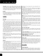
Battery Switch

Standby-loads, such as the automatic bilge


pumps and the stereo 

memory, are not affected by the battery switch since they are wired 
directly to the battery (see the Wiring Diagrams section of this 
chapter for more details).

Turn the battery switch to the Off position whenever the boat will 
be unoccupied for long periods of time.

Battery Switch Positions

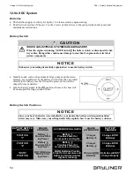
BATTERY SWITCH

POSITIONS

ENGINE

STARTING

ACCESSORIES & LIGHTS

ENGINE

ALTERNATOR

BATTERY 

CHARGER

POSITION

"1" 

Battery  1 

Provides Start-

ing Power

Battery  1 

Provides Power for

Accessories and Lights

Charges

Battery  1 

Charges BOTH

Batteries

POSITION

"2" 

 Battery  2 

Provides Start-

ing Power

Battery  2 

Provides Power for

Accessories and Lights

Charges

Battery  2 

Charges BOTH

Batteries

 "BOTH"

POSITION

BOTH Batteries 

Provide Start-

ing Power

BOTH Batteries Provide 

Power for Accessories and 

Lights (not advised unless 

engine is running)

Charges BOTH

Batteries

Batteries will 

NOT 

Charge Properly

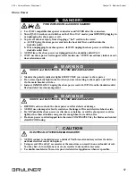
SHOCK & ELECTRICAL SYSTEM DAMAGE HAZARD! 

When the engine is running, NEVER turn Off the battery switch or disconnect the bat-
tery cables. Doing either could cause damage to your boat’s engine and/or electrical 
system components.

CAUTI ON

!

Make sure your selling dealer fully explains how to use the battery switch.

NOTI CE

BATTERY

SWITCH

Since your boat’s batteries were installed by your dealer, the battery switch positions listed 
below may vary. Make sure your selling dealer fully explains how to use the battery switches.

NOTI CE

Summary of Contents for 2005 289 Classic

Page 1: ......

Page 2: ......

Page 3: ...m the use of information contained herein Due to our commitment to product improvement Bayliner reserves the right to make changes in the product design specifications and equip ment at any time witho...

Page 4: ...ulsion Related Systems Engine 24 Bilge Blower System 24 Fuel System 25 Fuel Fill Vent 26 Fuel Filters 26 Anti siphon Valve 26 Quick Oil Drain System 27 Chapter 4 Controls Gauges Steering 28 Shift Thro...

Page 5: ...System 12 Volt DC System 49 Batteries 49 Battery Switch 49 Battery Switch Positions 49 Fuses 50 12 Volt DC Accessory Outlet 50 Alternator 50 Battery Charger If Equipped 50 110 Volt AC System 51 Shore...

Page 6: ...alerts you to hazards or unsafe practices which COULD result in severe personal injury or death if the warning is ignored WARNING This box alerts you to hazards or unsafe practices which COULD result...

Page 7: ...t in a secure yet readily available place Dimensions and Tank Capacities Layout View Dealer Service Your dealer is your key to service Ask your dealer to explain all systems before taking delivery of...

Page 8: ...rg In Canada for the CPS courses call 1 888 CPS BOAT U S Coast Guard Auxiliary 1 800 368 5647 or on the Internet at http www cgaux org Outside the United States your selling dealer national sailing fe...

Page 9: ...his supplement is included in your owner s packet Propeller Keep the propeller in good repair and at the correct pitch for your particular situation A slightly bent or nicked propeller will adversely...

Page 10: ...om the back deck or swim platform while the engine s are running Teak surfing dragging or water skiing within 20 feet of a moving watercraft can be fatal DANGER DANGER PERSONAL SAFETY HAZARD ALWAYS se...

Page 11: ...the zinc deteriorates including Water temperature Salinity Water pollution Stray electrical current Stray electrical current from your boat another boat or the dock may cause complete deterioration of...

Page 12: ...LWAYS securing the lifting slings together BEFORE lifting WARNING PERSONAL INJURY and or PRODUCT or PROPERTY DAMAGE HAZARD NEVER lift any boat using the cleats or the bow and stern eyes WARNING PERSON...

Page 13: ...n be fatal Breathing CO blocks the ability of your blood to carry oxygen The effects are cumulative even low levels of exposure can result in injury or death Factors That Increase the Effects of CO Po...

Page 14: ...CO can be present without the smell of exhaust fumes if exhaust fumes are detected on the boat take immediate action to dissipate these fumes Treat symptoms of seasickness as possible CO poisoning Get...

Page 15: ...g charring or deterioration is found Ensure that your engines and generators are properly tuned and well maintained Inspect each water pump impeller and the water pump housing Replace if worn Make sur...

Page 16: ...wer Squadrons U S Coast Guard Auxiliary 1 800 368 5647 or on the Internet at http www cgaux org U S Power Squadrons 1 888 FOR USPS 1 888 367 8777 or on the Internet at http www usps org United States...

Page 17: ...IM PLATFORM PORT HULLSIDE FRESHWATER TANK VENT STARBOARD HULLSIDE COCKPIT STEP DRAIN AFT BILGE PUMP DRAIN FORWARD BILGE PUMP DRAIN HOLDING TANK VENT HEAD SINK DRAIN GALLEY SINK DRAIN AIR CONDITIONER D...

Page 18: ...Chapter 2 Locations 289 Owner s Manual Supplement 12 Deck Views HORN GRAB RAILS BOW HATCH WIPER ROPE CHOCK ANCHOR ROLLER ANCHOR LOCKER ROPE CHOCK CLEAT STARBOARD BOW LIGHT PORT BOW LIGHT...

Page 19: ...2 Locations 13 Aft Deck View Side Deck Views PORT SIDE STARBOARD SIDE CLEAT CLEAT CLEAT CLEAT HOLDING TANK PUMP OUT DECK FITTING SHORE POWER INLETS FRESHWATER FILL DECK FITTING FUEL FILL DECK FITTING...

Page 20: ...PENDING ON ENGINE AND ACCESSORY OPTIONS NOTE TYPICAL HELM LAYOUT SHOWN VHF RADIO IF EQUIPPED MACERATOR SWITCH IF EQUIPPED SHIFT THROTTLE LEVER SPEEDOMETER DEPTH FINDER TACHOMETER 12 VOLT DC OUTLET IGN...

Page 21: ...Volt AC Master Panel Located forward of the head entry door Air Conditioner If Equipped Located in the center aft storage locker under the v berth mattress Air Conditioner Seawater Intake Seacock If E...

Page 22: ...ment 16 Batteries Located on the port side of the engine room Battery Charger Located on the port side of the engine room on the aft wall Battery Switch Located in the aft stor age hatch of the cockpi...

Page 23: ...ocations 17 Bilge Pumps 2 Total One is located in the engine room bilge forward of the engine One is located under the cabin entry step Blower Switch Located on the helm switch panel AFT BILGE PUMP FO...

Page 24: ...nitors 2 Total One is located in the salon above the aft dinette seat One is located in the aft berth on the bulkhead just aft of the side window Depth Finder Transducer Located in the engine room bil...

Page 25: ...hwater Fill Deck Fitting marked WATER Located on the port deck trail Freshwater Pump Located in the aft floor hatch in the cabin Freshwater Pump Switch Located in the galley behind the sink FRESHWATER...

Page 26: ...r s Manual Supplement 20 Freshwater Tank Located in the aft floor hatch in the cabin Fuel Fill Deck Fitting marked GAS Located on the aft deck Fuel Tank Located in the engine room FRESHWATER TANK FUEL...

Page 27: ...ccess through the aft wall hatch in the head Holding Tank Access through the for ward wall hatch in the aft berth Holding Tank Pump out Deck Fit ting Located on the starboard deck trail AFT WALL HATCH...

Page 28: ...e engine room bilge Marine Head Seawater Intake Seacock Located in the aft floor hatch in the cabin Navigation Lights Red and green running lights at the bow White all round light on the hardtop not s...

Page 29: ...Power Inlet s Located on the starboard deck Shower Drain Pump Switch Located in the head below the sink Trim Tab Hydraulic Fluid Res ervoir Located on the port aft wall of the engine room SHORE POWER...

Page 30: ...Chapter 2 Locations 289 Owner s Manual Supplement 24 Water Heater Located in the port forward cor ner of the engine room WATER HEATER...

Page 31: ...nning the boat below cruising speed FIRE and EXPLOSION HAZARD Fuel vapors can explode BEFORE starting the engine 1 Check the bilge areas for fuel vapors or leaking fuel If you see leaking fuel or smel...

Page 32: ...ser Yacht Owner s Manual and the fuel recommenda tions in the engine operation manual MUST be followed WARNING CAUTION Avoid the storage or handling of gear near the fuel lines fittings and tank Caref...

Page 33: ...e engine Periodically replace the fuel filters to make sure they remain clean and free of debris Talk to your selling dealer or local marina about fuel additives that help prevent fungus or other buil...

Page 34: ...es of hose including the oil drain plug can extend out of the bilge drain A 6 Re clip the draw cord section C to the draw cord section D 7 Push the oil drain hose oil drain plug and both sections of t...

Page 35: ...more steering system details Shift Throttle Controls Read all of the information about the shift throttle controls in the shift throttle manual the engine operation manual and the Cruiser Yacht Owner...

Page 36: ...e trim tabs are controlled by two rocker switches at the helm Check and refill the trim tab hydraulic fluid reservoir as directed in the trim tabs owner s manual For the location of the fluid reservoi...

Page 37: ...s may cause brief erratic readings on the tachometer This will not damage the tachometer gauge or affect its accuracy when not transmitting Fuel Gauge It is normal for the pointer on your fuel gauge t...

Page 38: ...ncerning VHF radio usage Compass accuracy can be affected by many factors Have a qualified technician calibrate your compass Make sure the technician gives you a deviation card which shows the correct...

Page 39: ...at switches and or switches at the helm The bilge pumps are wired directly to the battery Unless the battery is dead the pumps should work even when the boat is unattended NOTICE Discharge of oil oil...

Page 40: ...elow Checking for clogging debris 1 Remove the pump motor from the housing a Lift the tab while rotating the fins counter clockwise b Lift out the pump motor c Clear the housing of debris 2 Reinstall...

Page 41: ...rn On check the fuse on the fuse block If the fuse is good but the switch still does not work it may mean the switch is bad or the battery is dead 2 After testing push the test button all the way down...

Page 42: ...sheet for cleaning and maintenance information FLOODING and SWAMPING HAZARD Close the seacock s when leaving your boat unattended for any length of time If a seacock is left open a hose failure could...

Page 43: ...in use or when the freshwater tank is empty Inspect and clean the freshwater filter often the filter is located on the freshwater pump If your boat is to be left unattended for a long period of time...

Page 44: ...e side from filter 2 Open the faucet that is furthest away from the fresh water pump 3 Place the air nozzle against the end of the just removed water line and blow air through the system 4 When water...

Page 45: ...circuit breaker on the 110 volt AC master panel until the water heater tank is COMPLETELY filled with water The tank is full if water flows from the tap when the hot water is turned On in the galley...

Page 46: ...s Keep the deck drains free of debris Gray Water Gravity Drains The head sink and shower sink are above the waterline and are gravity drained overboard Shower Drain System Turn On the shower drain pum...

Page 47: ...r to rise in the bowl stop pumping until the water recedes Close the intake seacock when the system will not be used for long periods of time Winterizing the System Read the marine head s operation an...

Page 48: ...pump waste directly overboard where regulations permit 1 Open the overboard discharge seacock 2 Press both macerator switches at the same time to run the pump 3 Stop running the macerator as soon as...

Page 49: ...r vessel Pre wiring For Windlass The deck is pre wired to support the installation of a windlass Contact your selling dealer for help with choosing and installing a windlass PERSONAL INJURY and or PRO...

Page 50: ...jaw slides should not need to be adjusted If you decide to adjust the jaw slide positions obtain the correct mea surements from your selling dealer PRODUCT or PROPERTY DAMAGE HAZARD Take down and secu...

Page 51: ...Repeat steps one through seven on the other side Aft Curtains 1 Partially zip both aft curtain zippers to the canvas top and the aft side curtains 2 Start with the center aft cur tain snaps and work y...

Page 52: ...thods may remove the waterproof finish of the fabric and may also decrease the life of the polyester thread used in the canvas Reapply a water repellent treatment as needed Method 1 1 Add 1 8 cup 2 oz...

Page 53: ...sh the clear vinyl with soap and water 3 Rinse thoroughly to remove the soap 4 Before stowing the clear vinyl must be completely dry Air drying is best but you can also carefully dry the vinyl with a...

Page 54: ...ances and entertainment systems If applicable make sure the AC breaker is turned On for the appliance or entertainment system you wish to use Refrigerator The refrigerator runs on 12 volt DC power unl...

Page 55: ...nguisher in the galley area Do NOT use the stove while underway Any non cooking devices on or near your stove during use are potential fire hazards Do NOT touch the burners grates or nearby surfaces a...

Page 56: ...e can be removed and the dinette area can be converted into a berth 1 Lift the table A and remove the table leg B 2 Place the table A so that it fits securely on the edge lips C at the front of the di...

Page 57: ...as required 4 The bulb base may be corroded clean the base and coat it with non conductive electrical lubricant Interior Exterior Lights The lights are powered by the boat s 12 volt DC system The batt...

Page 58: ...strainer for debris before each use of the air condi tioning system If the strainer needs to be cleaned out follow the directions in the Seawater Systems section of Chapter 6 in this Supplement CARBO...

Page 59: ...maintenance or activation of electri cal devices 1 Check the bilge areas for fuel vapors or leaking fuel If you see leaking fuel or smell fuel vapors a Do NOT start the engine do NOT turn On any elec...

Page 60: ...ides Start ing Power Battery 1 Provides Power for Accessories and Lights Charges Battery 1 Charges BOTH Batteries POSITION 2 Battery 2 Provides Start ing Power Battery 2 Provides Power for Accessories...

Page 61: ...arger manual The battery charger will automatically charge your boat s batteries when 110 volt AC power is being provided by shore power and the battery charger circuit breaker on the 110 volt AC mast...

Page 62: ...E HAZARD Do NOT turn On the water heater circuit breaker on the 110 volt AC master panel until the water heater tank is COMPLETELY filled with water The tank is full if water flows from the tap when t...

Page 63: ...turns On when you are connecting to shore power do NOT turn On the main breaker switches Instead IMMEDIATELY unplug the shore power cord ALWAYS from the dockside outlet first and alert marina managem...

Page 64: ...ter panel 5 As needed turn On the individual component breakers on the 110 volt AC master panel Parallel Switch Only if Equipped with Dual Shore Power When only one dockside outlet is available you ca...

Page 65: ...ess Routings NOTE VIEW IS UNDERSIDE OF DECK WINDLASS PLUG PRE WIRE WIPER COMPASS HEAD LIGHT DASH WINDLASS SWITCH PLUG PRE WIRE COURTESY LIGHT INTERIOR LIGHTS INTERIOR LIGHTS INTERIOR LIGHT STARBOARD B...

Page 66: ...12 Volt DC Hull Harnesses Routing System 110 Volt AC Hull Harness Routings ENGINE AFT BILGE PUMP TO DECK HARNESS SHOWER DRAIN PUMP FUEL TANK FORWARD BILGE PUMP REFRIGERATOR BATTERY CHARGER TO DECK HE...

Page 67: ...Manual Supplement Chapter 12 Electrical System 61 Battery Cable Routings POSITIVE BATTERY CABLES ARE RED NEGATIVE BATTERY CABLES ARE YELLOW NOTES BATTERIES BATTERY SWITCH ENGINE GROUND ENGINE POSITIV...

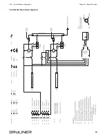
Page 68: ...Chapter 12 Electrical System 289 Owner s Manual Supplement 62 Wiring Diagrams 110 Volt AC Electrical System...

Page 69: ...289 Owner s Manual Supplement Chapter 12 Electrical System 63 12 Volt DC Electrical System...

Page 70: ...Chapter 12 Electrical System 289 Owner s Manual Supplement 64 Engines Electrical System View not available at time of printing Periodically check www bayliner com for updates...

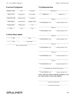
Page 71: ...ter Type Propeller Manufacturer Pitch Model Number Generator Manufacturer Model Name Number Serial Number Oil Type SAE Quarts Filter Type Fuel System Fuel Capacity Filter Type Key Numbers Ignition Oth...

Page 72: ...Make Type Hull Color Trim Color Fuel Capacity Engine Type Number of Engines Distinguishing Features Distinguishing Features Operator of Boat Full Name Male or Female Age Health Address Address Phone...

Page 73: ...rture Time Stopover 1 Arrive No Later Than Date Arrive No Later Than Time Stopover 2 Arrive No Later Than Date Arrive No Later Than Time Stopover 3 Arrive No Later Than Date Arrive No Later Than Time...

Page 74: ...Owner s Notes...

Page 75: ......

Page 76: ...Part Number 1781926 Bayliner P O Box 9029 Everett WA 98206 360 435 5571...

Reviews: