


(A)
(B)
(C)
TECNO 28-LM
TECNO 38-LM and 50-LM
D862
D863
D864
7
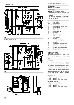
ELECTRICAL SYSTEM
as set up by the
manufacturer
LAYOUT (A)
Burner TECNO 28-LM
LAYOUT (B)
Burners TECNO 38-LM and 50-LM
•
Models TECNO 38-LM and 50-LM leave the
factory preset for
400 V
power supply.
• If
230 V
power supply is used, change the
motor connection from star to delta and
change the setting of the thermal cut-out as
well.
Key to Layout (A) - (B)
C
- Capacitor
CMV
- Motor contactor
LAL 1.25 - Control box
F1
- Protection against radio interference
FR
- Photocell
MB
- Terminal strip
MV
- Fan motor
PO
- Oil pressure switch
RT
- Thermal cut-out
S1
- Switch for following operations :
MAN = manual
AUT = automatic
OFF
S2
- Button for :
-
= power reduction
+ = power increase
SM
- Servomotor
TA
- Ignition transformer
TB
- Burner ground (earth) connection
VM
- Delivery pump valve
VS
- Delivery pump valve (safety valve)
VU
- Valve on nozzle return
ELECTRICAL CONNECTIONS
set by installer
Use flexible cables according to regulation EN
60 335-1:
• if in PVC boot, use at least H05 VV-F
• if in rubber boot, use at least H05 RR-F.
All the cables to be connected to the burner ter-
minal strip 5)(C) must be routed through the fair-
leads, supplied by the manufacturer for insertion
into the holes in the plate, preferably those on the
left side, after having unscrewed screws 6), split
the plate into its two parts 7) and 8) then re-
moved the thin diaphragm effectively closing the
aperture.
The fair leads and precut holes can be used in
various ways. One example is given below:
TECNO 28-LM
1 - Pg 11 Single-phase power supply
3 - Pg 9
Control device TL
4 - Pg 9
Control device TR or probe (RWF40)
TECNO 38-LM and 50-LM
1 - Pg 11 Three-phase power supply
2 - Pg 11 Single-phase power supply
3 - Pg 9
Control device TL
4 - Pg 9
Control device TR or probe (RWF40)


