


35
C607215 - GB
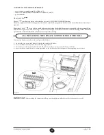
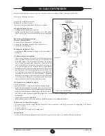
INSTRUCTIONS FOR FITTERS
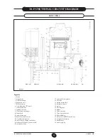
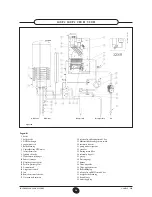
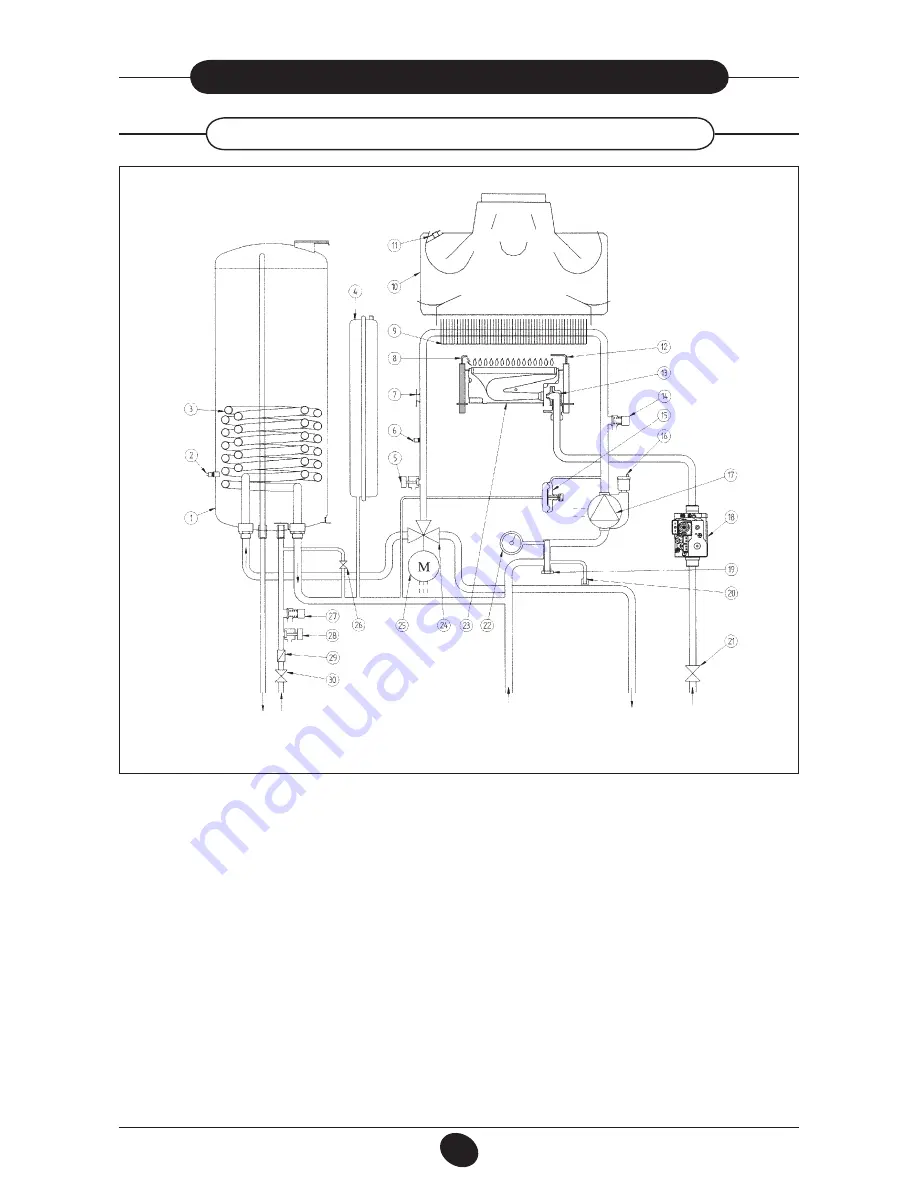
30. FUNCTIONAL CIRCUIT DIAGRAM
1 boiler
2 boiler probe
3 DHW exchanger
4 Expansion vessel
5 Boiler drain tap
6 Central heating NTC sensor
7 Safety thermostat
8 Ignition electrode
9 Water-fumes exchanger
10 fumes hood
11 fumes thermostat
12 flame detection electrode
13 Gas train with injectors
14 safety valve on heating circuit 3 bar
15 differential hydraulic pressure switch
16 automatic air vent
DHW outlet
DHW inlet
Heating return
Heating delivery
Gas
17 pump with air separator
18 Gas valve
19 heating return filter
20 automatic by-pass
21 gas tap
22 Pressure gauge
23 Burner
24 Three-way valve
25 Three-way valve motor
26 Boiler filling tap
27 safety valve on DHW circuit 8 bar
28 storage boiler drain tap
29 flow adjuster
30 water supply tap
240 i - 280 i
Figure 19
0702_1204 / C
G_1884
Legend :


