


Supplied By www.heating spares.co Tel. 0161 620 6677
4.0 Site Requirements
9
4.1
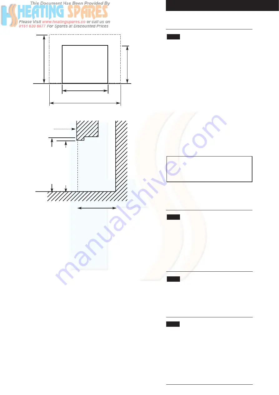
Builders Opening
(Fig. 5)
1. The boiler unit is designed to fit within a
standard builders opening, the minimum
dimensions of which are as shown.
Height
584mm (23in)
Width
584mm (23in)
Depth
375mm (14
3
/
4
in)
2. The opening should be soundly constructed of
brick, pre-cast concrete or be a proprietary
builders opening.
3.
The base of the opening should be sound
and non-combustible and must be flat and
level.
4. The base of the builders opening should be at
the same height as the finished level of the
hearth.
IMPORTANT:
If a false chimney breast is
intended to house the boiler, a simulated
builders opening, within the breast, must be
provided.
5. The builders opening must not communicate
with voids, pipe ducts or spaces other than the
room in which the appliance is situated.
4.2
Location
1. The appliance must be installed in the living
space of a dwelling.
2. Restrictions to the siting of the appliance are
covered by BS 5546. The appliance may not be
installed in bathrooms, shower rooms, bedrooms
or bed sitting rooms.
4.3
Fireplace Opening & Surround
1. If a fireplace surround is to be used, it must be
centrally placed and have opening sizes and a
vertical flat area as detailed in the Installation and
Servicing Instructions for the fire.
4.4
Frame Extension Kit
1. If the depth of the builders opening is less than
the 375mm minimum specified, it can be
increased by the use of the Frame Extension Kit.
2. Kit N
o
234887 is suitable for use with Inset 2
TS, BS and FS models.
For Inset 2 KS & CS, Kit N
o
239341 must be used.
3. Full installation details are included in the kit.
1
560mm (22in) min
SURROUND OR FINISHED
WALL FACE
560mm (22in) minimum
590mm (23
5
/
8
) maximum
584mm (23in) minimum
375mm (14
3
/
4
in)
minimum
Solid, non combustible hearth
to support the boiler,
as specified in BS 5871.
HEARTH
LEVEL
When correctly installed the centre line of the boiler flue socket
will be 260mm from the surround or finished wall face.
Fireplace
Opening
460mm (18in) min
560mm (22in) max
584mm (23in) min
590mm (23
15
/
64
in) max
584mm (23in) min
NOTE:
For builders openings
between 343mm & 374mm the
optional Frame Extension Kit must
be used.
Fig. 5


