


3.7
Function Programming
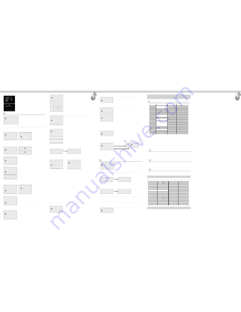
FUNCTION PROGRAMMING
1 PRESET
2 VECTORSCAN
3 PATTERN
4 SECTOR SETUP
5 MASK ZONE
6 MASK COLOR
7 MOTION
1. Move the joystick left/right or press
OPEN to enter Function Programming options.
2. Move the joystick up/down to move the cursor to select the pre shot options.
3. Move the joystick Left/Right or press
OPEN to enter preset options.
Preset option:
3.7.3
Pattern
1. Joystick Up / Down to move the cursor to select Pattern.
2. Joystick Left / Right or press OPEN to enter the menu.
Pattern Operation Steps:
FUNCTION PROGRAMMING
1 PRESET
2 VECTORSCAN
3 PATTERN
4 SECTOR SETUP
5 MASK ZONE
6 MASK COLOR
7 MOTION
1. Number
2. Set Preset
3. Call Preset
4. Delete Preset
5. Name
PRESET
1 NUMBER 1
2 SET PRESET
3 CALL PRESET
4 DELETE PRESET
5 NAME _____________
6 NAME DISPLAY OFF
1 - 50 64 - 77 102 - 165
001
0123456789
IRIS CLOSE WHEN DONE
INPUT RANGE:
PRESET
1 NUMBER 1
2 SET PRESET
3 CALL PRESET
4 DELETE PRESET
5 NAME _____________
6 NAME DISPLAY OFF
Call Preset:
PRESET
1 NUMBER 1
2 SET PRESET
3 CALL PRESET
4 DELETE PRESET
5 NAME _____________
6 NAME DISPLAY OFF
PRESET
1 NUMBER 1
2 SET PRESET
3 CALL PRESET
4 DELETE PRESET
5 NAME _____________
6 NAME DISPLAY OFF
ARE YOU SURE TO DO THIS?
3.7.1
Preset
(1.) Move the joystick left / right or press OPEN to enter the number editing programming.
PS: Program the number of preset position.
(2.) Move the joystick left / right to select “0 - 9”,press “OPEN” to confirm, press “CLOSE” to exit.
(1.) Move the joystick up / down to move the cursor to select the Name.
(2.) Move the joystick left / right or press OPEN to enter name editing menu.
(3). Move the joystick left / right to select “A - Z / 0 - 9” , press “OPEN” to confirm, press “CLOSE” to change or exit.
6. Name Display
(1.) Move the cursor to select preset position.
(2.) Move the joystick left/right or OPEN to enter the setting(ensure the preset position data you desire to save)
(3). Press OPEN to finalize your selection, then the screen displays STORED and return to the previous menu level.
Or press CLOSE to return to the previous menu level. without save your selection
STORED
IRIS OPEN WHEN DONE
1. Move the joystick left/right or press OPEN. The lens auto switch to current
preset position corresponding to the edited number.
Delete Preset:
IRIS OPEN TO CONFIRM
IRIS CLOSE TO CANCEL
Press OPEN to confirm the selection and exit. Press CLOSE to cancel the
selection and exit.
Program the desired deleting number referring to Number Setup
Section so as to select the preset position to be deleted.
Move the cursor to select Delete Preset
Move the joystick left/right or press
OPEN to enter the Delete Preset.
1. Move the cursor to select name display.
2. Move the joystick left / right to set ON or OFF of the name display.
PRESET
1 NUMBER 1
2 SET PRESET
3 CALL PRESET
4 DELETE PRESET
5 NAME _____________
6 NAME DISPLAY OFF
PRESET
1 NUMBER 1
2 SET PRESET
3 CALL PRESET
4 DELETE PRESET
5 NAME _____________
6 NAME DISPLAY OFF
WELCOME________
ABCDEFGHIJKLMN
OPQRSTUVWXYZ
0123456789_
IRIS OPEN WHEN DONE
IRIS CLOSE TO EXIT
PLEASE ENTER:
Setup On / Off display on the direction name preset:
Function: User can make different auto scan according to various inspection.
3.7.2
Program Vector Scan
1. Joystick Up / Down to select Program Vector Scan.
2. Joystick Left / Right or press OPEN to enter the programming.
3. Joystick Up / Down to select pending programming serial number
(number range:1 - 6).
4. Move the Joystick to select and enter the items to Program a Vector Scan
FUNCTION PROGRAMMING
Programming Vector Scan instruction:
1 PRESET
2 VECTORSCAN
3 PATTERN
4 SECTOR SETUP
5 MASK ZONE
6 MASK COLOR
7 MOTION
I: Name
Pr: stands for Preset Position.
Vs: stands for Vector Scan.
Pt: stands for PTZ Tour.
II: Number Programming-selection based on the name.
III: SP-Set up the speed of Preset.
IV: Dwell
Vector scan running operation steps:
I: Select pending Vector scan track in Number menu
II: Joystick Up / Down to select Vector scan
III: Joystick Left / Right or press OPEN to run the selected Vector scan track
Vector scan track deletion steps:
I: Select pending deleting vector scan track in Number menu.
II: Joystick Up / Down to select Delete a Vector Scan.
III: Joystick Left / Right or press OPEN to delete the selected vector scan track.
VECTORSCAN
(items include: name / number / SP / dwell).
1 NUMBER 1
2 PROGRAM A VECTORSCAN
3 RUN A VECTORSCAN
4 DELETE A VECTORSCAN
PROGRAM VECTORSCAN 1
NAME NUM SP DWELL
IRIS CLOSE WHEN DONE
1.
2.
3.
4.
ARE YOU SURE TO DO THIS ?
IRIS OPEN TO CONFIRM
IRIS CLOSE TO CANCEL
PLEASE WAIT...
Function: User can program three traces simulating manual operation.
Function: User can program three traces simulating manual operation.
Running Pattern Tracking Operation Steps:
PATTERN
1 NUMBER 1
2 PROGRAM A PATTERN
3 RUN A PATTERN
4 DELETE A PATTERN
5 NAME ______
6 NAME DISPLAY OFF
3.7.4
Sector Setup
3.7.5
Mask Zone
3.7.6
Mask Color
1. Number
(1.) Joystick left / right or press OPEN to select the sector number (number range:1 - 8).
1. Number
2. Mask Edit
3.Mask Display
(1.) Joystick Up / Down to move the cursor to select NUMBER.
(2.) Joystick Left / Right to select pending editing mask areas (from area1-24).
(1.) Joystick Left / Right to set up the display name of ON / OFF.
(1.) Joystick Up / Down to move the cursor to select Mask Zone.
(2.) Joystick Left / Right or press OPEN to enter editing.
(3.) Press OPEN to edit the mask zone, capture the mask point. Press NEAR, FAR
(set the mask area in pan action), WIDE, TELE (set the mask area in tilt action) to
adjust the area of mask zone. Press CLOSE to exit when done and return to
upper stage menu.
1. Mask color
2. Semi-transparency
(1.) Joystick Up / Down to move the cursor to select MASK COLOR.
(2.) Joystick Left / Right to move the cursor to select the Mask color.
1. Move the joystick left / right or press OPEN to enter the Motion
(1.) Action
①
. Move the joystick left / right or press OPEN to enter the Action panel.
②
. Joystick left / right to select Action. Action by
:
None / Preset / Vector
Scan / Pattern / Pan Scan / Auto Scan.
(2.) Number
(1.) Joystick Up / Down to move the cursor to select SEMI-TRANSPAREN.
(2.) Joystick Left / Right to set up the Semi-transparency of ON / OFF.
2. Pan Start POS
(1.) Move the joystick left / right or press OPEN to select a Pan Start Point.
(2.) IRIS OPEN when done or IRIS CLOSE to exit without saving.
3. Pan End POS
(1.) Move the joystick left / right or press OPEN to select a Pan End Point.
(2.) IRIS OPEN when done or IRIS CLOSE to exit without saving.
(1.) Move the joystick left / right or press OPEN to select a Pan End Point.
(2.) IRIS OPEN when done or IRIS CLOSE to exit without saving.
4. Tilt Start POS
(1.) Move the joystick left / right or press OPEN to select a Pan Start Point.
(2.) IRIS OPEN when done or IRIS CLOSE to exit without saving.
5. Tilt End POS
(1.) Joystick Up / Down to move the cursor to select Name Display of ON or OFF.
6. Name
(1.) Select the sector name and press OPEN to enter name editing.
(2.) Edit the name referring to preset setup instruction.
7. Name Display
3. Joystick Up / Down to select pending operating or programming
Pattern (number range:1 - 3).
4. Joystick Up / Down to move the cursor to select Program a Pattern.
5. Press OPEN to enter recording of the manual running trace. as left Fig 1.
6. Press CLOSE to finalize the selection. as left Fig 2.
7. Joystick Up / Down to move the cursor to select NAME.
8. Edit name (Please refer to name setting section of preset position)
9. Joystick Up / Down to move the cursor to select Name Display.
1. Select pending running Pattern trace from NUMBER.
2. Joystick Up / Down to select Run a Pattern.
3. Joystick Left / Right or press OPEN to run the trace of selected Pattern.
Delete Pattern Operation Steps:
1. Select pending Delete Pattern trace from NUMBER.
2. Joystick Up / Down to select Delete a Pattern.
3. Joystick Left / Right or press OPEN to enter and Click OPEN to delete
the trace of selected Pattern as below Fig 3 - Fig 4
1. Move the joystick up / down to
move the cursor to select sector setup.
FUNCTION PROGRAMMING
Sector Setup:
1 PRESET
2 VECTORSCAN
3 PATTERN
4 SECTOR SETUP
5 MASK ZONE
6 MASK COLOR
7 MOTION
2. Move the joystick left / right or press
OPEN to enter the setting.
SECTOR SETUP
1 NUMBER 1
2 PAN START POS 0.0
3 PAN END POS 0.0
4 TILT START POS 0.0
5 TILT END POS 0.0
6 NAME ________
7 NAME DISPLAY OFF
IRIS OPEN to begin
IRIS CLOSE when done
Fig 1
Fig 3
Fig 4
Fig 2
Press
OPEN
MASK ZONE
1 NUMBER 1
2 MASK EDIT
3 MASK DISPLAY OFF
Mask Color
1 MASK COLOR GRAY 5
2 SEMI-TRANSPARENCY OFF
3.7.7
Motion
<< Function
:
The lens will auto return to the assigned preset position or
perform certain motion using command set by user when the camera
does not receive orders from controlling device.
MOTION
1 PARK ACTION
2 POWER ON ACTION
3 LIMIT OPERATION
PARK ACTION
1 ACTION NONE
2 NUMBER 1
3 PARK TIME NA
①
. Select the Number and press OPEN or move the joystick left / right to
enter Number editing.
②
. Setup method: referring to preset setup instruction.
(3.) Park Time
①
. Select the Park Time and press OPEN or move the joystick left / right to
enter Park Time (time range:1-999).
②
. Setup method: referring to preset setup instruction.
3.8
System Setup
PARK ACTION
1 CLEAR MEMORY
2 RESTOR DEF SETTING
3 COLOR SYSTEM NTSC
4 DOME RESET
5 IR MODULE SETUP
3.8.1
Clear Memory
POWER ON ACTION
1 ACTION VECTORSCAN
2 NUMBER 1
LIMIT OPERATION
1 START POSITION 0.0
2 END POSITION 0.0
3 DIRECTION RIGHT
4 OPERATION OFF
ARE YOU SURE TO DO THIS?
IRIS CLOSE TO CONFIRM
IRIS OPEN TO CANCEL
PLEASE WAIT...
Press
OPEN
2. Select the Power on Action and move the joystick left / right or
press OPEN to enter the Power on Action.
3. Move the joystick left / right or press OPEN to enter the Limit Operation.
1. Joystick Up / Down to move the cursor to select Clear Memory.
2. Joystick Left / Right or press OPEN to enter.
3. Press OPEN to Clear Memory or press CLOSE to cancel.
3.8.2
Restore Default Setting
3.8.3
Color System
ARE YOU SURE TO DO THIS?
IRIS CLOSE TO CONFIRM
IRIS OPEN TO CANCEL
PLEASE WAIT...
Press
OPEN
1. Joystick Up / Down to move the cursor to select Restore Def Setting.
2. Joystick Left / Right or press OPEN to enter.
3. Press OPEN to Restore Def Setting or press CLOSE to cancel.
1. Joystick Up / Down to move the cursor to select Color System.
2. Joystick Left / Right to select the PAL or NTSC.
3.8.4
Dome Reset
1. Joystick Up / Down to move the cursor to select Dome Reset.
2. Joystick Left / Right or press OPEN to reset the dome.
1. Joystick Up / Down to move the cursor to IR CONTROL.
2. Joystick Left / Right to select the IR control AUTO / MANUAL.
3. Joystick Up / Down to move the cursor to IR SW DELAY.
4. Joystick Left / Right to select the IR Switch delay 5SEC / 10SEC / 15SEC / 30SEC / 45SEC.
3.8.5
IR Module Setup
(1.) Select the Action and move the joystick left/right or press OPEN to
enter Action. Action includes: None / Preset / Vector Scan / Pattern
/ Pan Scan / Auto Scan
(1.) Start Position
(2.) End Position
Refer to End Position setting section
(3.) Direction
Move the joystick left / right to select the Direction (left or right).
(4.) Operation
Select the OPERATION and move the joystick left / right set up the Operation of ON / OFF.
(2.) Select the Number and move the joystick left/right or press OPEN to enter.
Setup method: refer to preset setup instruction.
Move the joystick left / right
or press OPEN
Press open to save and exit, or press close to exit
IRIS OPEN WHEN DONE
IR MODULE SETUP
1 IR CONTROL AUTO
2 IR SW DELAY 10SEC
Chapter 6 Troubleshooting of Dome Device
1. Problem description:
Power switched on with no response, fail to lock motor and no image.
Possible reason:
Problems with power circuit
Solution:
Check if the power cable is connected to power of AC24V.
2. Problem description:
Camera rotates normally, but with no text display and no image
Possible reason:
The text display is switched off
Solution:
Switch on the text display according to the menu instruction
3. Problem description:
After self-detection of the dome device, menu cannot be displayed
Possible reason:
Incorrect operation
Solution:
Call+95+ACK to open
4. Problem description: Distorted character or image
Possible reason:
Interfered by external electronic signal (noise) or the camera is directed to the an electronic image
Solution:
Grounding the dome device or shut off the surrounding big electronic devices(electric, HF,
signal generating) equipment, or rotate the camera
5. Problem description:
Self-detection is normal, but failed to control the device.
Possible reason:
Incorrect settings or improper/incorrect connection of circuit setting
Solution:
Set the protocol, baud rate and address of dome device and check the circuit
6. Problem description:
Difficulties with controlling dome camera
Possible reason:
Improper or incorrect circuit connection
Solution:
Check the control circuit
7. Problem description:
Periodic actions performed automatically
Possible reason:
Respective functions are set to perform automatically
Solution:
Switch off relevant automatic functions
8. Problem description:
Camera makes a clicking noise that disappears after 15 seconds
Possible reason:
The camera is performing vertical positioning
Solution:
This is a normal event, and no solution is required
Chapter 4 Short-Cut Operations and Specification
of Dome Device
4.1
Short-Cut operation table
51
52
53
55
56
57
58
59
60
61
62
63
79
80
81
82
83
84
85
86
87
88
89
Pan-Tilt Control
Background light compensation*
Day/Night*
Camera related OSD*
Digital zoom*
Focus*
Iris*
White balance*
Set line scanning mode
Run pattern
Run vector
Picture freeze*
Record line
scanning speed
Start line scanning
On
Auto
Camera menu On \ Off
On
Auto
Auto
Auto
Indoor
ATW
Long distance
Run pattern 1
Run pattern 2
Run pattern 3
Run vectors can 1
Run vectors can 2
Run vectors can 3
Run vectors can 4
Run vector scan 5
Run vector scan 6
On
Run cruise track
Set line scanning starting point
Set line scanning ending point
Off
Color
Camera function OSD On\Off
Off
Manual
Manual
Manual
Outdoor
One push WB
Short distance
Off
Control Object
Pan-Tilt Control
Call preset position
Save preset position
Number of
preset position
4.2
Description of “Cruise Track” Function:
4.3
Description of “Line-Scanning” Function:
4.4
Intelligent Manually Pan Continuous Scan:
Notes:
1.These functions differs depending on different types of camera.
Preset point of the position: 1-50, 64-77,102-165 (totally 128)
Function short - cut preset point: 51-63, 78-101
Preset point setting:
Press “No.” + “Shot.” + “ON” .
Call Preset point:
Press “No.” + “Shot.” + “ACK”.
Clear Preset point:
Press “No.” + “Shot.” + “OFF”.
Description of the preset point :
Note : Dome operation will be different due to controller’s different specs.
Dynamic preset point
Reserve
Dome reset
Main menu
Set the auto flip
Pan continuous scanning
Call dynamic preset point
Reset dome
Call main menu
On
On
Off
91
92
93
94
95
96
101
a
)
When enter “51+SHOT+ON”, the device is enabled system default cruise track. The device will auto scan point by point from
No.1 preset position to No.16 preset position. If certain position has not been preset or been cleared after preset, “cruise
track” will not scan them.
b
)
Dwell time of the preset position is 2 seconds.
c
)
About other 6 cruise tracks operation, please refer operation manual of the keyboard controller. Different controller is with
different operation.
a) Dome device will auto line-scan between two specified points.
b) User can set the start point by “52+SHOT+ON” and end point by “53+SHOT+ON”.
c) Line scanning speed set: user keep a manual line scan speed three seconds above, then through“51+SHOT+ACK” to save the
speed as line scan speed, use“52+SHOT+ACK” to enable the line scan.
d) Dwell time of line-scanning between “starting point” and “ending point” is 2 seconds.
When user use joystick for pan scan monitoring, keep manually 3 seconds, then press “
101+SHOT+ACK
”, the dome can go on
with the scan speed and monitor position automatically .
Chapter 5 Specifications
Scanning System
Effective Picture Elements
Image Sensor
Digital Signal Processing (DSP)
Synchronizing System
Horizontal Resolution
Video S/N Ratio
Min Illumination (approx.)
Video Out Level
Optical Zoom
IR LED Effective Range
White Balance
Auto Gain Control (AGC)
Wide Dynamic Range (WDR)
High Light Compensation (HLC)
3D Digital Noise Reduction (DNR)
Day / Night
Electronic Shutter
Motion Detection
Privacy Masking
Sens-Up
EIS Electronic Anti-Shake
OSD Language
Pan Preset Speed
Tilt Preset Speed
Manual Speed Pan
Manual Speed Tilt
Preset Points
Motion Detection
Scanning Speed
Pattern
OSD Language
Communication
Ingress Protection
Relative Humidity
Operating Temperature
Power Supply
Shell Size (mm)
Weight
Installation Type
Mounting brackets
PAL NTSC
795(H)X596(V) 811(H)X508(V)
1/4" EX-View CCD
LG XDI
Internel / Line Lock LL
540TVL (Color) / 570TVL
(
B/W
)
More than 52dB(AGC Off)
1Vp-p
(
75Ω), Composite
23X
120 - 150 meters
Auto / Push / Manual (1800°K - 10,500°K)
Off / Low / Middle / High
WDR -
On / Off
Off / Low / Middle / High
IR CUT
1/50 - 1/100,000
4 Zones
8 Zones
Auto / Fix
:
X2,X4,...X512
On / Off
Chinese / English
240°/s
150°/s
0°- 180°/s
0° - 55°/s
128
Yes,6 different area
0.5° - 60°/s
8 minutes
Chinese / English
RS-485
IP 66
10% - 90%
–10
℃
- 50
℃
AC 24V / 3A
355 (H) × 210 (W)
7.5 kg
Wall Mount / Hanging
Optional
PTW-983IR
Color
:
0.003
(
0.6
)
Lux
(
Sens up Off) /
B/W
:
0.0001
(
0.1
)
Lux
(
Sens-up Off
)
• CAMERA REBOOT: To reboot the camera system.
• FACTORY RESET: To reset the camera setting to factory setting, select
[FACTORY RESET] option.
Reset Settings
1. Select [RESET] option.
2. Press [EXIT] button and the RESET menu appears.
3. Use [up] or [down] to select option.