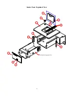
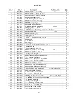
background image


10

Parts List 


Item # 

Part # 

              Description                                     Includes Item 

    Qty. 

      1 

28022592 

BD2 Teller Door Assembly                                2,3 

       1 

      2 

28023021 

BD2 Teller Door Hinge Section 

       1 

      3 

28023031 

BD2 Teller Door Handle Section 

       1 

      4 

28024191 

BD Handle Brush Strip 

       2 

      5 

12002211 

Multi Opening Wire Grommet 

       1 

      6 

28007023 

BD3 Laminated Countertop 

       1 

      7 

28027022 

BD3 Mounting Angle 

       2 

      8 

28012592 

BD2 Back Panel Assembly 

       1 

      9 

00592991 

Replacement Lock Assembly                            10,11 

       1 

     10 

00537041 

TD Opaque Lock Label 

       1 

     11  

06926040 

1-3/8” Universal Bushing – w/Flexible Shutters 

       1 

     12 

28010592 

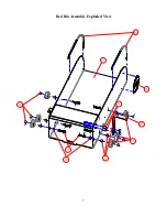
BD2 Bin Assembly                                            13,21 

       1 

     13 

28035011 

BD2 Red Bin Edging 

       2 

     14 

00537031 

TD Stop Label 

       1 

     15 

13025011 

1/2 OD x 1/4 ID x 1in Steel Spacer 

       1 

     16 

28008031 

BD Handle 

       2 

     17 

28003011 

Skate Wheel 

       6 

     18 

28009011 

Wheel Spacer 

       6 

     19 

95282930 

1/4-20 x 1-3/4 Button Socket Cap Screw 

       8 

     20 

95006001 

1/4 Flat Washer 

       2 

     21 

95005002 

1/4-20 Nylon Locking Nut 

       8 

     22 

28013592 

BD2 Customer Door Assembly                         23 

       1 

     23 

28020021 

BD2 Customer Door Gasket 

       1 

     24 

92005002 

6-32 Nylon Locking Nut 

       2 

     25 

28017021 

BD Right Customer Door Latch SM 

       1 

     26 

92026006 

#6 x 1/8 Brass Standoff 

       2 

     27 

28014022 

BD Customer Door Arm Right SM 

       1 

     28 

28016011 

BD Customer Door Pivot Block 

       2 

     29 

28019031 

BD2 Customer Door Catch 

       1 

     30 

28017011 

BD Left Customer Door Latch SM 

       1 

     31 

28014012 

BD Customer Door Arm Left SM 

       1 

     32 

24085993 

TDR Mic/Call Panel Assembly              (33,34,35,40,41,42) 

       1 

     33 

22151991 

Black Rainshield Mic Kit 

       1 

     34 

00353991 

Call Button Replacement Kit 

       1 

     35 

00207012 

Polyester Call Button Label 

       1 

     36 

24085992 

TDR Speaker Panel Assembly                (37,38,39,40,41,42) 

       1 

     37 

02909991 

2x3 Speaker w-5/32in Mounting Holes 

       1 

     38 

02909051 

2x3 Speaker Backbox 

       1 

     39 

91025001 

4-40 Nylon Locking Nut 

       4 

     40 

93100623 

#8 x 5/8 Philips Pan SMS SS 

       2 

     41 

24086032 

Audio Panel Lower Mount 

       2 

     42 

24086022 

Audio Panel Upper Mount 

       2 

     43 

94068201 

3/16 x 1/8-1/4 Grip Rivet 

       8 

Summary of Contents for Basic Manual Transaction Drawer 3

Page 1: ...Road Maineville Ohio 45039 513 677 0500 Basic Manual Transaction Drawer 3TM BD3TM BD3 1 TM Installation and Service Manual Copyright 2016 E F Bavis Associates Inc Revised 05 31 2016 All Right Reserved...

Page 2: ......

Page 3: ...llation 2 Service Information 3 Troubleshooting 3 Fig 1 Mounting Flange Assembly 4 Fig 2 Removing Back Panel Illustration 5 Exploded Parts Diagram 6 9 Parts List 10 Basic Drawer 3 BD3 Dimensions 11 Ba...

Page 4: ......

Page 5: ...not to approach when the drawer is open Full 14 extension of drawer No wiper or sliding type weather seals Our seals are replaceable and operate in compression to reduce wear and provide the best pos...

Page 6: ...ght 7 Test Drawer operation Installation with the Window Installed Drawer Retrofit 1 Verify that the opening dimensions are correct 2 Remove the inside Back Panel See Fig 2 3 Remove the 4 screws that...

Page 7: ...rocedure to reinstall the back panel Drawer Bin Removal To remove the Red Bin it is necessary to remove the back panel as stated above and then remove the two bolts and spacers attaching the operator...

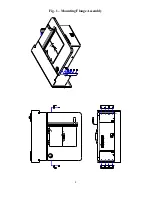
Page 8: ...4 Fig 1 Mounting Flange Assembly...

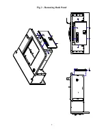
Page 9: ...5 Fig 2 Removing Back Panel...

Page 10: ...6 Inside Parts Exploded View...

Page 11: ...7 Red Bin Assembly Exploded View...

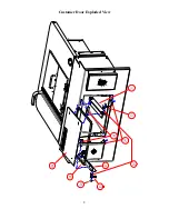
Page 12: ...8 Customer Door Exploded View...

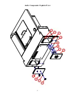
Page 13: ...9 Audio Components Exploded View...

Page 14: ...1 4 Flat Washer 2 21 95005002 1 4 20 Nylon Locking Nut 8 22 28013592 BD2 Customer Door Assembly 23 1 23 28020021 BD2 Customer Door Gasket 1 24 92005002 6 32 Nylon Locking Nut 2 25 28017021 BD Right Cu...

Page 15: ...OR DRAWER MINIMUM WALL OPENING 28 3 4 WIDE X 10 1 8 TALL MAXIMUM WALL OPENING 30 1 2 WIDE X 13 1 2 TALL IF THE SITE DIMENSIONS EXCEED THE RANGE OF ANY OF THE DIMENSIONS LISTED CONTACT THE FACTORY WHIL...

Page 16: ...FOR DRAWER MINIMUM WALL OPENING 28 3 4 WIDE X 10 1 8 TALL MAXIMUM WALL OPENING 30 1 2 WIDE X 11 3 4 TALL IF THE SITE DIMENSIONS EXCEED THE RANGE OF ANY OF THE DIMENSIONS LISTED CONTACT THE FACTORY WH...

Page 17: ...tance from the drive surface to the bottom of the moving bin is 32 to 40 Actual distance is to be determined by others Dimensions shown are for reference only BD3 shown 36 5 8 35 13 16 6 29 13 16 40 D...

Page 18: ......

Reviews: