


Description of the Software Modules and Parameters
Parameter manual
b maXX
BM5800
Document No.: 5.16029.03
663
3
4
Accept the measured motor parameters and the dead time compensation for the motor
control in the self-optimization.
5
Setting of both compensating controllers (for HF injection and voltage model). A basic
setting can be made with ProDrive.
6
Setting of the smoothing time for the determined actual speed value, proposed value
range between 1 and 5 ms. The greater the inertia of the drive is, the greater the
smoothing time may be selected.
7
Set speed controller (at sensorless operation a torque inertia measurement is not pos-
sible).
8
Store data set.
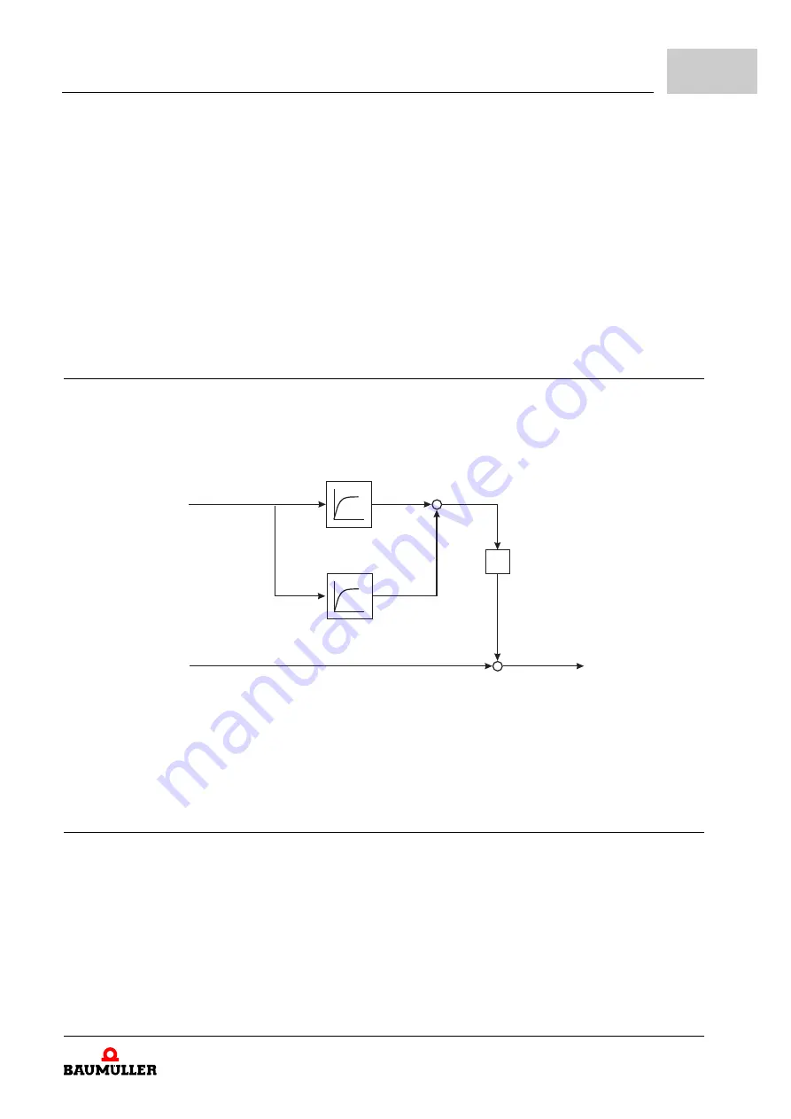
3.9.1.3 Vibration damping
Vibrations can occur in the controlled operation during low speed. These vibrations can
be damped with an additional speed set value. Here the high-frequency component of the
Iq-I term is filtered and added to the speed set value.
Figure 178:
Control diagram of the vibration damping
The I-term is guided through a slow filter (
) and a fast filter (
) and the
difference is then multiplied by a damping factor (
). This value is added to the
speed set value.
3.9.1.4 Motor diagnosis
In general the motor diagnosis checks if the notch position search with injection, the set
frequency (
) and the band width (
) works and
therefore as well if a motor can be operated encoderless with injection. For this, the highly
frequent voltage is injected in the motor and thereby the electrical angle is slowly in-
creased by discrete steps. Then, the resulting demodulated signal is assigned to the an-
gle in ProDrive (see figure) and can be evaluated. The motor diagnosis is started via the
bit 4 of
.
d
-
+
(P133.55)
Iq-I part (P47.22)
Tfast (P133.58)
Tslow (P133.59)
nset (P18.21)
nact (P18.22)


