background image

Baumer Hübner

Description

 | 

4

V1 | PMG10 & PMG10P SSI

Operating Manual

9

4

Description

4.1

Rotary encoder

1

9

8

2

5

3

4

10

7

6

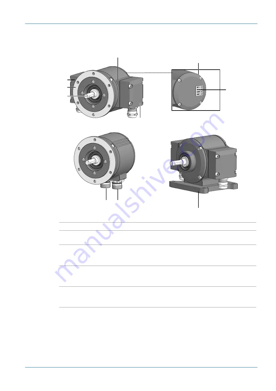
Ill. 1: 

Description PMG10

1

Housing

2

Cover

3

LED activity indicator

4

Housing base B3 (according to product
variant)

5

Radial flange connector: SSI, additional
incremental output 1 (optional), program-
ming interface (PMG10P only)

6

Radial flange connector: additional incre-
mental output 2 (option), speed switch
(option)

7

Radial terminal box: SSI, additional incre-
mental output 1 (optional), programming
interface (PMG10P only)

8

Solid shaft with key

9

EURO flange B10 (according to product
variant)

10

Radial terminal box: additional incremen-
tal output 2 (optional), speed switch (op-
tional)

Summary of Contents for Hubner Berlin PMG10

Page 1: ...V1 3 15 2022 11171693 EN US Operating Manual PMG10 PMG10P SSI Absolute Encoder...

Page 2: ...ls 10 5 Installation 11 5 1 Mounting with EURO flange B10 11 5 1 1 Attach coupling onto encoder shaft 11 5 1 2 Mounting encoder onto drive shaft 12 5 2 Mounting with base B3 14 5 2 1 Attach coupling o...

Page 3: ...0 6 10 Z PA SDL 1 WLAN adapter Programming device for HMG10P PMG10P 31 6 11 Sensor cable and round connector 31 6 11 1 Sensor cable 31 6 11 2 Round connector M23 32 6 11 3 Round connector M23 17 pin w...

Page 4: ...eviations are at the discretion of Baumer at all times 1 2 Warnings in this manual Warnings draw attention to potential personal injury or material damage The warnings in this manual indicate differen...

Page 5: ...s 9C C9 50 00 A6 EE www baumer com Made in Germany XXXXL305 1 2 3 4 1 Product name product code material number 2 Serial number technical data MAC ad dress 3 Baumer Website 4 Labels 1 7 Maintenance an...

Page 6: ...Electrical and Electronic Manufacturers Association ZVEI INFO warranty seal Any breaking of the seal provided at the device will result in loss of warranty 1 9 Temperature range for operation and stor...

Page 7: ...ct for installation Out puts not in use must not be wired Unused wires of cable outputs must be insulated Do not go below the permissible cable bending radii Disconnect the system from power before th...

Page 8: ...oon as it is detected Damages can only be claimed within the applicable claims deadlines In case of externally visible transport damage proceed as follows Instruction a Do not accept the delivery or o...

Page 9: ...flange connector SSI additional incremental output 1 optional program ming interface PMG10P only 6 Radial flange connector additional incre mental output 2 option speed switch option 7 Radial termina...

Page 10: ...available as accessory 2 Mounting device customer specific for EURO flange B10 mount 3 Mounting screw M6x16 mm for attach ment device ISO 4017 for EURO flange B10 mount 4 M6x20 mm screw for fastening...

Page 11: ...s Sticky liquids may damage sensing unit and ball bearings Disassembling a device which is stuck to the axis can lead to destruction a Do not use adhesive liquids to fasten the device 5 1 Mounting wit...

Page 12: ...re power supply is and remains discon nected DANGER Explosion Sparks may cause fire or explosion a Do not use the device in the near vicinity of explosive or highly flammable materials NOTICE Equipmen...

Page 13: ...t direct water ingress c Apply grease onto the drive shaft d Mount the attachment device customer specific to the drive using the fastening screws e Push coupling onto the encoder shaft and tighten to...

Page 14: ...ial pressure 1 Ill 5 Attach coupling onto encoder shaft 1 Coupling Tools n 2 5 mm Instruction a Mount the coupling on the encoder shaft observe the related mounting instructions b When using the K 35...

Page 15: ...or explosion a Do not use the device in the near vicinity of explosive or highly flammable materials NOTICE Severe runout errors of the drive shaft reduce service life and may cause angular errors Sev...

Page 16: ...ording to product vari ant Tools n 2 5 mm n 10 mm Instruction a Prior to installation check the drive runout error and dimensions b Mount the encoder in a way ensuring the electrical connection is pro...

Page 17: ...the drive shaft imposed on coupling parts may damage the ball bearings a Prevent any hard impacts of the drive shaft on coupling parts Instruction a Mount the drive with small angular error and parall...

Page 18: ...lie face to face can damage the rotary en coder a Make sure that the coupling claws do not block b Make sure that there is no direct axial stop on the device shaft Instruction w Observe the distances...

Page 19: ...pply a Operate the sensor only with protected low voltage and safe electrical isolation of protection class III NOTICE Sensor damage or unintended operation due to work on live parts Work on live part...

Page 20: ...Error output nE System OK Error output inverted PRE RESET DIR Sense of rotation SP II DSL_OUT1 speed switch open collector III or semiconductor relay III SP II DSL_OUT2 Speed switch 0 V III or semico...

Page 21: ...he current posi tion to 0 default INFO The RESET input has no influence on the incremental signals The RESET input has no influence on the speed switch INFO 4 30 V DC applied at the RESET input during...

Page 22: ...V HTL Transmission length 550 m bei 100 kHz n 550 m bei 100 kHz TTL n 350 m bei 100 kHz HTL Output frequency 600 kHz n 600 kHz TTL n 350 kHz HTL I The TTL HTL output Vin Vout at the additional output...

Page 23: ...d After initialization and speed being ns off High impedance overspeed ns off speed ns on Status unchanged Device rotation within this speed range during initialization results in status low impedance...

Page 24: ...make sure the specified protection class is being en sured INFO Connection cables are not included in delivery 3 1 2 6 5 4 Ill 10 Connecting the supply cable 1 Torx slotted screw M4x32 mm 2 Terminal...

Page 25: ...al 25 d Insert the supply cables into the cable gland let stick out approx 50 mm of cable e Assign the supply cables to the terminals f Attach the cable gland to the terminal box g Mount the terminal...

Page 26: ...at the outputs a Make sure that no operating voltage is present at the outputs SSI Programming interface programmable product variant only Additional output incremental 1 optional 4 12 3 2 1 6 7 8 11...

Page 27: ...parate voltage supply 4 11 3 2 1 5 6 7 10 9 8 12 13 14 Ill 12 Pin assignment 1 dnu SP I 2 dnu A II 3 dnu A II 4 dnu B II 5 dnu B II 6 Ub II 7 0 V II 8 dnu SP I 9 nE II 10 nE II 11 dnu R II 12 dnu R II...

Page 28: ...mm Tools n 24 mm n 27 mm n Crimping or soldering tool depending on connector Instruction a Push cable through inside the housing and insulate b Open the shield and place it around c Insulate each indi...

Page 29: ...that no operating voltage is present at the outputs SSI Programming interface HMG10P only Additional output incremental 1 optional 10 9 8 7 6 5 4 3 2 1 12 11 14 16 15 13 17 Ill 13 Flange socket M23 ma...

Page 30: ...ltage is present at the outputs Additional incremental output 2 optional Speed switch optional The TTL HTL output Vin Vout at the additional incremental output 2 is galvanically isolated and requires...

Page 31: ...s enable parameterization according to encoder version n Resolution Singleturn SSI n Resolution Multiturn SSI n Binary or Gray Code SSI n Additional output 1 and 2 number of pulses per revolution n Sw...

Page 32: ...ise CCW ordering designation 11068577 n Suitable for second flange connector 62 mm 26 2 mm X 8 7 6 5 4 3 2 1 9 12 10 11 8 7 6 5 4 3 2 1 9 17 13 16 14 15 10 11 View X 17 pin View X 12 pin Also see abou...

Page 33: ...Yellow 0 14 mm2 DIR 3 Black 0 14 mm2 SB I 4 5 White Black 0 14 mm2 PRE 6 Brown 0 14 mm2 SA I 7 Brown red 0 5 mm2 Ub 8 Green red 0 22 mm2 C 9 Green black 0 22 mm2 C 10 Brown blue 0 5 mm2 0V 11 II Black...

Page 34: ...2 1 9 17 13 16 14 15 10 11 View X 17 pin PIN Core color Core cross section MOVEMENT xMG10 1 Grey 0 14 mm2 nE 2 White Yellow 0 14 mm2 DIR 3 Black 0 14 mm2 SB I 4 Blue 0 14 mm2 nE 5 White Black 0 14 mm...

Page 35: ...y constraining force a Never apply force If properly performed all components can be uninstalled smoothly b Use only suitable tools to uninstall NOTICE Equipment damage by adhering liquids Sticky liqu...

Page 36: ...ft DANGER Burns caused by heat The device heats up at high speeds There is a risk of getting burned after use a Avoid overheating the device b Wear suitable protective gloves and clothing 1 2 3 Ill 16...

Page 37: ...electrical connections b Loosen the the coupling on the drive shaft Observe the notes in the data sheet and the coupling assembly instructions c Loosen the encoder from the drive s attachment device...

Page 38: ...eat The device heats up at high speeds There is a risk of getting burned after use a Avoid overheating the device b Wear suitable protective gloves and clothing 1 2 3 4 1 Ill 17 Uninstall encoder moun...

Page 39: ...Tools n 2 5 mm n 10 mm Instruction a Disconnect all electrical connections b Loosen the the coupling on the drive shaft Observe the notes in the data sheet and the coupling assembly instructions c Rem...

Page 40: ...ata sheet and declaration of conformity Programming interface RS485 600 m I Programmable parameters Resolution Singleturn and Multiturn SSI II Binary or Gray Code SSI II Additional output ppr number I...

Page 41: ...ance IEC 60068 2 6 Vibration 30 g 10 2000 Hz IEC 60068 2 27 Shocks 400 g 1 ms Corrosion protection see data sheet and declaration of conformity Weight approx 1 9 kg III Connection Terminal box 2x III...

Page 42: ...e connectors Ill 19 Dimensions of the solid shaft encoder with EURO flange B10 with radial flange sockets all in mm unless specified otherwise 8 2 Solid shaft encoder dimensions with housing base B3 I...

Page 43: ...di tional output II 22 Ill 10 Connecting the supply cable 24 Ill 11 Pin assignment 26 Ill 12 Pin assignment 27 Ill 13 Flange socket M23 male 17 pin clockwise 29 Ill 14 Flange socket M23 male 12 pin cl...

Page 44: ...www baumer com worldwide 144508811...

Reviews: