


Baumer_EAx_PROFINET_EN_202011_MNL.docx
41/74
www.baumer.com
11.20
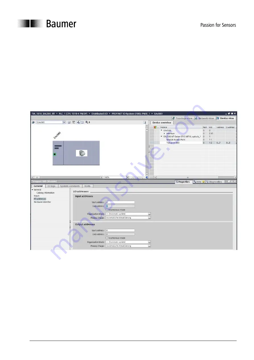
5.4.2.1. Address assignment within the process image
Access to the encoder input and output data takes place
via addresses within the PLC’s process image.
Here, address and process image are assigned.
Mark
the projected telegram in the encoder’s device view. Click on module window „I/O addresses“ to open
the input field.
Enter the start address of the respective address range or accept the system’s proposal. Identical or
overlapping addresses for input and output are allowed. Make sure addresses are within the cyclic update
range of the process image.
The process image will be that of the cyclic main program OB1 (not synchronized).
“Automated Update“ as
shown in the screenshot below means system-selected settings, but also manual input is allowed.
5.4.2.2. Selecting the update time
The check boxes „clock synchronous operation“ unchecked will set encoder to RT mode.
Device view -> Interface allows you to select
at “Update time” whether the encoder position value shall
update with every clock pulse transmitted. Not every application requires updating at such high clock rate.
Under certain circumstances, update with every 2nd, 4th or 8th clock pulse transmitted will suffice and save
bandwidth at high bus load. Which reduction factor to choose depends on the selected real time class and
transmit clock pulse and is seen in the options provided in the drop-down menu.


