G 120 II V
Page 24
1st Edition, Rev. 0 Chg. 2
3.1.8.4
Removing the IK120 II C & G, 2nd Stage Valves.
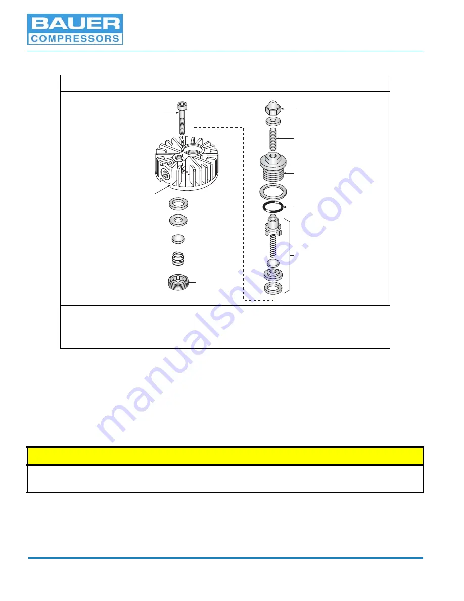
See Figure 3-12 and proceed as follows:
1. Remove the intake and pressure lines from the Valve Head (7).
2. Remove the screws (8) holding the Valve Head onto the cylinder.
3. Insert two 8 mm diameter metal pins, any length, in the holes in the Valve Head and secure them in
a vise with the valve head on top.
4. Using the special valve tool, remove the Intake Valve (6) (See Figure 3-13).
5. Turn the Valve Head over and replace it on the metal pins.
6. Remove the Cap Nut (1).
7. Unscrew the Stud (2) approximately five turns.
Figure 3-12
IK120 II C & G, 2nd Stage Valve Head and Valves
1. Cap Nut
2. Stud
3. Pressure Plug
4. O-ring
5. Pressure Valve Insert
6. Intake Valve
7. 2nd Stage Valve Head
8. Allen Screw
^
CAUTION
In order to avoid damaging the special tool or the valve when using the tool, ensure that it is pushed prop-
erly and firmly into the valve bore so that it will not tilt when it is turned.
1
2
3
4
5
6
7
8


