by
B A T H O L O G Y
8
Fan Installation
A t m o s p h e r i c 320
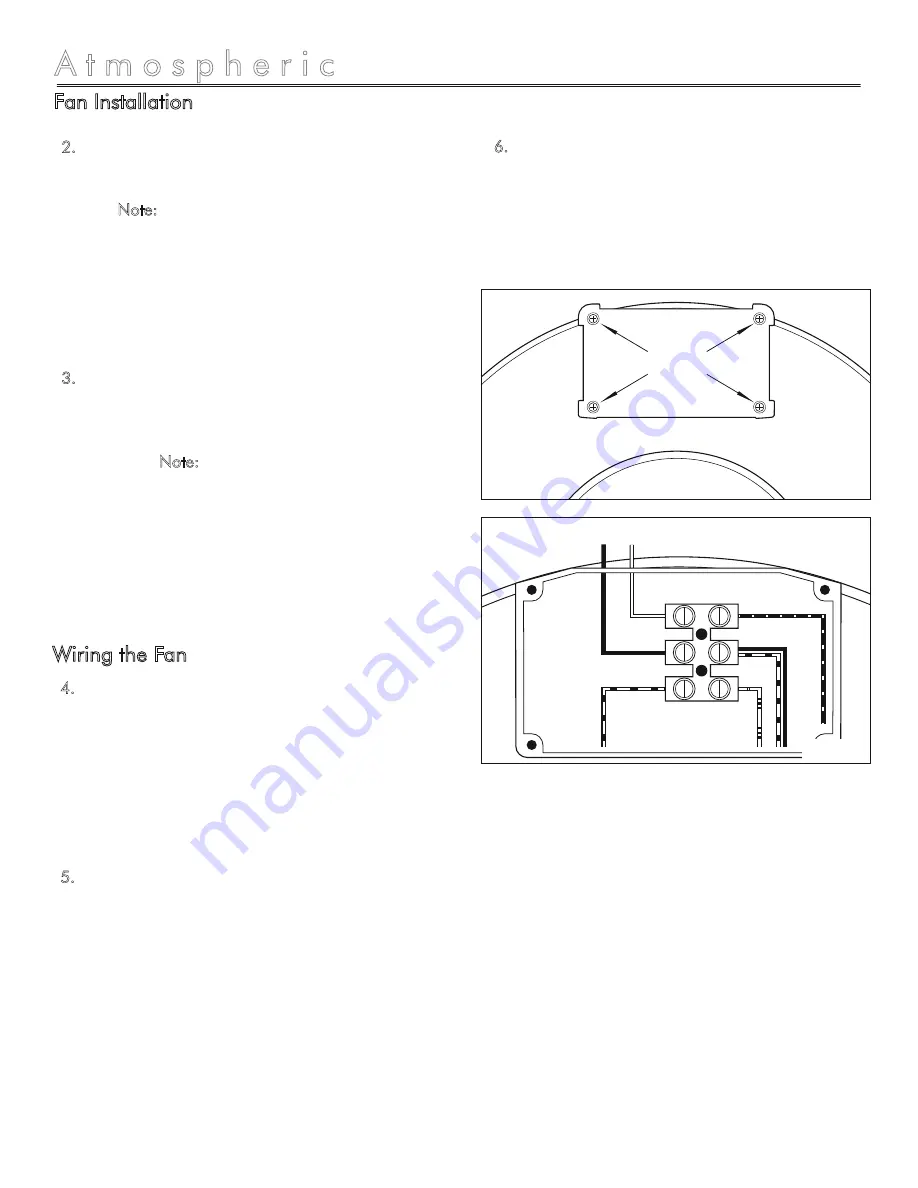
Remove the screws securing the terminal box
cover plate located on the side of the fan (1)
(
see figure 3
). All fan motor connections are
pre-wired to an electrical terminal strip. A 3/8”
romex type cable restraint connector will be
needed to secure the wiring through the
knockout provided on the side of the terminal
box.
Bring incoming electrical service through the
romex connector and the fan knockout. Be
sure to place the connector nut over the wiring
coming into the terminal box. There are two
open ports on the terminal strip. Using a small
regular screwdriver, tighten the neutral (white)
wire of the incoming supply under the open
terminal strip port labeled “N”. Tighten the line
(black) wire of the incoming supply under the
open terminal strip port labeled “L”. Since the
fan motor is isolated within a plastic housing,
grounding is not necessary (
see figure 4
).
4.
5.
Secure the romex connector. Secure the
incoming supply with the romex connector.
Replace the fan terminal box cover. All fan
motor and capacitor connections have been
pre-wired from the factory. No additional fan
wiring is necessary.
6.
Using the 1” wood screws (4) provided, attach
the fan mounting bracket (2) to a support beam
at the selected location (
see figure 1 on page
6
). Note: Fan (1) mounting can be at any
point along the duct and in any angle;
however, vertical mounting is recommended to
reduce condensation buildup in the fan (1). If a
horizontal installation is necessary and
condensation buildup may pose a problem,
wrap insulation around the fan (1).
Attach fan (1) to the mounting bracket (2) with
the three 7/16" sheet metal screws (5)
provided, making sure the wiring box is
positioned for easy access (
see figure 2 on
page 6
). Note: Bracket (2) is provided with
rubber vibration isolation grommets (3) to
prevent the transmission of sound through the
structure. Be careful not to overtighten. Also,
care should be taken not to strip the
plastic
housing
. Screws (5) are selftapping and do not
require pilot holes. However, pilot holes no
larger than 3/32" are recommended.
2.
3.
Wiring the Fan
Screws
N
L
Figure 4
Figure 3
Black
White
Blue
Brown
Black / Red
Red
Supply from Electronic Timer Control / Slide Speed Control


