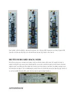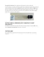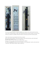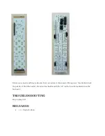
Now to ensure that the headers are properly aligned, screw the hex screw and the standoff on bottom
board. Place the female headers on button board with the male pins inserted. Now place top board, screw
with the standoff screw and finally, solder the headers to both boards. Just like in the image below.
Unscrew the top spacer again and disconnect the two boards.
Place the three potentiometers to their respected places on the board. Push them well until they
sit
absolutely flat on the board
, but don’t solder them yet.
Next, place the mono jacks on the board, the LEDs and the switches.
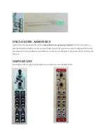
The LEDs are
polarized
so make sure that the long leg (+) is facing upwards. Also the notch on led and
circuit board should match. Still don’t solder anything yet.


