Bastian Solutions RLVDC Installation And Maintenance Manual Download Page 12


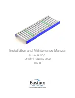
  Installation and Maintenance Manual: RLVDC


Published February 2022


Rev. B 


12


6.2.2  Electrical Service 

  All Bastian Solutions’ conveyor DC products operate at either 24V or 48V, nominally. 

  If adjustment of control card settings is required, refer to the respective technical manual listed in 

Reference Documents, or contact Bastian Solutions Customer Service at 

[email protected]

. 

  If there is a need to replace a DC control card, perform the following: 

o

  De-energize associated power supply and remove respective side cover (if applicable) 

o

  Adjust settings of replacement control card to match those of the existing control card. 

o

  Remove the existing control card from the side frame for ease of cable disconnection: 

  If the existing control card has a mounting plate, remove wiz nut securing control 

card mounting plate to side frame. 

  If the existing control card is secured to the conveyor side frame with anything 

other than a mounting plate, install new securing material on the new control card 

and re-use the securing material on the side frame. 

o

  One at a time, remove all cables and connectors and plug them into the same respective 

connection port on the new control card. 

o

  If the control card in question has a mounting plate, remove the mounting plate secured 

to the existing control card, and install it on the new control card (if the new control card 

does not already have a mounting plate installed on it). 

o

  Install the new control card on the conveyor side frame 

o

  Re-energize associated power supply, check the lane for proper system functionality, and 

reinstall respective side cover (if applicable). 


Never “hot swap” control cards (i.e. disconnect and reconnect power 

connector on control cards without de-energizing respective power supply). 

When doing this, there is an increased risk of damaging the new control 

card. 


There is always a possibility that control card errors are being caused by 

faulty communication cables (RJ45, CAT5, or CAT6), or problems with 

adjacent cards connected via the communication cables. 

  If cards or card fuses are blowing:


o

  Ensure there are no shorts in system power wiring


o

  Ensure all conveyor side frames are electrically bonded and provided a direct connection 

to earth ground


o

  Ensure control card DIP switch settings match those needed for zone MDR (if applicable)


o

  If associated conveyor zone has powered brake roller, ensure it is electrically connected


o

  If problems persist, refer to the respective technical manual listed in the Reference 

Documents section of this document.


  If experiencing any other electrical problems with Bastian Solutions DC conveyor, contact Bastian 

Solutions Customer Service at 

[email protected]

. 


When performing electrical work on Bastian Solutions conveyor, ensure 

adherence to all applicable OSHA standards. 

Summary of Contents for RLVDC

Page 1: ...Installation and Maintenance Manual Model RLVDC Effective February 2022 Rev B...

Page 2: ...ineer Checker Ben Baker Senior Design Engineer Approver Chris Perry Engineering Manager Revisions DATE REVISION DESCRIPTION AUTHOR 10 21 2019 A1 Initial Document Creation Josh Foiles 10 8 21 A2 Reform...

Page 3: ...s MDR Motorized drive roller DC powered conveyor roller with an internally mounted motor which may be controlled via internal or external commutation OAW Overall width of any given conveyor bed OD Out...

Page 4: ...11 6 2 2 Electrical Service 12 6 2 3 Replacing Rollers 13 6 2 4 Replacing Bands 15 7 Troubleshooting and Repair 17 8 Standard Spare Parts 18 List of Figures Figure 1 RLVDC General Arrangement Explode...

Page 5: ...ll ZoneControl User Manual Interroll DriveControl User Manual Interroll EC100 110 User Manual Interroll EC310 User Manual Itoh Denki HBM604 User Manual Itoh Denki IBE User Manual Itoh Denki HB510 User...

Page 6: ...t that are not explicitly described in this manual are considered out of scope Please contact Bastian Solutions for any questions or support that is not clearly addressed in this document Bastian Solu...

Page 7: ...iliar with the components and terminology used in this manual These terms will be used throughout the manual and are common among many of the other Bastian Solutions conveyor product lines Figure 1 RL...

Page 8: ...ic number given to a piece of equipment A mark number is usually made up of a single product line RZPDC RLVDC BZPDC etc but can contain many bed section lengths They can range from two inches to hundr...

Page 9: ...of product integrity during shipping accessories and supports may be delivered on separate but labeled skids 4 3 Skid Documentation All shipments will contain a Bill of Lading for the delivery compan...

Page 10: ...r s top of conveying surface 4 Place the support type that the layout designates Each support type has a corresponding mark sticker 5 Check the flow direction on the mark stickers to ensure that conve...

Page 11: ...f the equipment prior to engaging drive Ensure that all areas are clear of objects prior to loading and unloading No personnel should ever ride climb step sit on or otherwise put body weight on the co...

Page 12: ...card and install it on the new control card if the new control card does not already have a mounting plate installed on it o Install the new control card on the conveyor side frame o Re energize asso...

Page 13: ...until reaching the roller band that is being replaced The directions in this segment refer to replacement of rollers within a 3 roller center conveyor For motor driven rollers MDRs 1 Follow the lockou...

Page 14: ...s the frame Be careful NOT to apply a side load to the hex shaft Refer to Figure 5 Figure 5 MDR Removal 2 6 Provide upward force on the roller body until the hex is sitting above the side frame Refer...

Page 15: ...ough the bands 8 Once the new roller is through both bands guide the hex shaft into the hex hole 9 After the hex shaft is in the hex hole the opposite side shaft can be inserted into the appropriate h...

Page 16: ...x shaft into the appropriate hex hole Use the roller s length as leverage to aid in this step As called out in the roller replacement procedure use a putty knife or other flat surface tool to protect...

Page 17: ...Issues ERROR CAUSE ACTION Conveyor flow direction speed or acceleration is incorrect Incorrect DIP switch settings Check card manufacturer s literature to verify proper switch configuration Zone not...

Page 18: ...Table REF NO DESCRIPTION COMMON CONFIGURATIONS 1 ROLLERS 2 GROOVE POLYVEE 2 BANDS O RING 2IN ROLLER SPACING O RING 3IN ROLLER SPACING POLYVEE 2IN ROLLER SPACING POLYVEE 3IN ROLLER SPACING 3 MOTOR DRIV...

Page 19: ...Solutions It may not be duplicated used or disclosed without written permission from Bastian Solutions It may not be used in whole or in part for any purpose other than its intended purpose as an ope...

Reviews: