


2
3
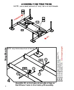
Assembly Instructions
Pages 6 - 15
First Use / Adjustments
Page 16
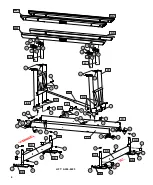
Parts List and Diagrams
Pages 4 - 5, 13 - 14
INDEX
Warning
Page 2, 3
Warranty
Page 20
Do not play on or near the lift.
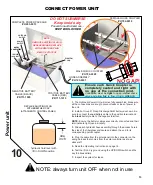
Leave your automatic bilge pump turned on the
automatic setting to prevent the accumulation of
rain water.
Service your lift regularly.
Do not service the unit with the boat on the lift.
Use a mooring line for additional security.
Visually inspect all parts and assemblies for
defects and damage prior to assembling the
lift.
Do not install the lift alone.
Install the lift on firm and level ground.
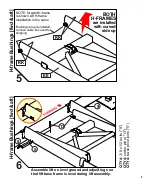
Verify the lower frame of the lift is level
Turn the power off during periods of non-use.
Manufactured under numerous U.S. and foreign patents.
For a complete list, visit bastaboatlifts.com/patents
before each use.
Troubleshooting / FAQ
Page 18
Maintenance
Page 19
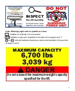
Never exceed lift capacity set
forth in manual and on H-frame
of the boat lift. Improper use or
failure to follow this instruction
can cause property damage,
serious injury, or death.
Never use for lifting humans
or animals. Improper use
or failure to follow this
instruction can cause
property damage, serious
injury, or death.
Always carefully review complete
manual before any assembly or use of
the product. Improper use or failure
to follow instructions or warnings in
manual can cause property damage,
serious injury, or death.
WARNING
STAY
CLEAR!
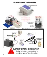
Always use AGM batteries and follow battery manufacturer’s
warnings and instructions. Improper use, or use of other
batteries, have the potential to produce flammable hydrogen
gas which can result in serious injury or death.
Always avoid being under, and maintain
adequate clearance from, the boat lift.
Failure to follow this instruction can
cause serious injury or death.
DANGER
Do not exceed the maximum weight capacity
specified for the lift.
DANGER
MAXIMUM CAPACITY
In the following pages various symbols are used:
indicates an illustration for a procedure.
indicates a major part described in the parts list on pages 4 and 5.
or indicate hardware items shown above and described in the parts list
on pages 4 and 5.
1&2
23
AA
1
INSPECT
the lift monthly
for frayed hoses, loose
fasteners and corrosion
lift unattended
6
,
7
00
lbs
3,0
39
kg


