


BE1-79S General Information
1-3
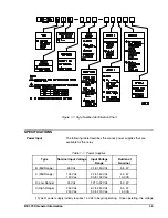
Figure 1-1. Style Number Identification Chart
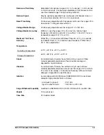
SPECIFICATIONS
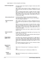
Power Input
The following table describes the various power supplies that are
available for this relay.
Table 1-1. Power Supplies
Type
Nominal Input Voltage
Input Voltage
Range
Burden at
Nominal
B (Mid Range)
48 Vdc
24 to 150 Vdc
5.5 W
C (Mid Range)
125 Vdc
120 Vac
24 to 150 Vdc
90 to 132 Vac
4.0 W
10.0 VA
D (Low Range)
24 Vdc
12† to 32 Vdc
5.0 W
X (High Range)
250 Vdc
240 Vac
62 to 280 Vdc
90 to 270 Vac
5.0 W
14.0 VA
† Type D power supply initially requires 14 Vdc to begin operating. Once operating, the voltage
Summary of Contents for BE1-79S
Page 26: ...BE1 79S Installation 4 5 Figure 4 5 S1 Case Panel Drilling Diagram Semi Flush Mounting...
Page 28: ...BE1 79S Installation 4 7 Figure 4 8 Voltage Sensing Circuit Connections...
Page 29: ...4 8 BE1 79S Installation Figure 4 9 RI RC and 52b Sensing Circuit Connections...
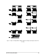
Page 30: ...BE1 79S Installation 4 9 Figure 4 10 Internal Connection Diagram With Power Supply Status...