9190700990 Rev F
BE1-67N Functional Description
i
SECTION 3
•
FUNCTIONAL DESCRIPTION
TABLE OF CONTENTS
INTRODUCTION.................................................................................................................................... 3-1
CURRENT SENSING ............................................................................................................................ 3-1
VOLTAGE SENSING............................................................................................................................. 3-2
DIRECTIONAL ELEMENT..................................................................................................................... 3-2
Zero Sequence Current Polarization.................................................................................................. 3-2
Zero Sequence Voltage Polarization.................................................................................................. 3-3
OVERCURRENT ELEMENTS............................................................................................................... 3-4
Time Overcurrent Element ................................................................................................................. 3-4
Instantaneous Overcurrent Elements................................................................................................. 3-5
Operate Time...................................................................................................................................... 3-5
OUTPUT CONTACTS ........................................................................................................................... 3-5
Relay Failure Output Contact ............................................................................................................. 3-5
Tripping Output Contacts ................................................................................................................... 3-5
Auxiliary Output Contacts................................................................................................................... 3-5
POWER SUPPLY .................................................................................................................................. 3-6
TARGETS .............................................................................................................................................. 3-6
Internally Operated Targets................................................................................................................ 3-6
Current Operated Targets .................................................................................................................. 3-6
Figures
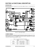
Figure 3-1. Function Block Diagram .......................................................................................................... 3-1
Figure 3-2. Zero Sequence Current Polarizing Phase Relationship ......................................................... 3-3
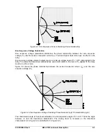
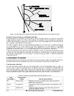
Figure 3-3. Zero Sequence Voltage Polarizing Phase Relationship (0
Characteristic Angle)................. 3-3
Figure 3-4. Zero Sequence Voltage Polarizing Phase Relationship (60
Characteristic Angle)............... 3-4
Tables
Summary of Contents for BE1-67N
Page 2: ......
Page 6: ...iv BE1 67N Introduction 9190700990 Rev F This page intentionally left blank...
Page 8: ...vi BE1 67N Introduction 9190700990 Rev F This page intentionally left blank...
Page 10: ...ii BE1 67N General Information 9190700990 Rev F This page intentionally left blank...
Page 18: ...1 8 BE1 67N General Information 9190700990 Rev F This page intentionally left blank...
Page 20: ...ii BE1 67N Controls and Indicators 9190700990 Rev F This page intentionally left blank...
Page 26: ...ii BE1 67N Functional Description 9190700990 Rev F This page intentionally left blank...
Page 34: ...ii BE1 67N Installation 9190700990 Rev F This page intentionally left blank...
Page 39: ...9190700990 Rev F BE1 67N Installation 4 5 Figure 4 4 Case Dimensions Rear View...
Page 43: ...9190700990 Rev F BE1 67N Installation 4 9 Figure 4 7 Typical Internal Connections...
Page 46: ...4 12 BE1 67N Installation 9190700990 Rev F This page intentionally left blank...
Page 48: ...ii BE1 67N Testing 9190700990 Rev F This page intentionally left blank...
Page 58: ...ii BE1 67N Characteristic Curves 9190700990 Rev F This page intentionally left blank...
Page 72: ...A 14 BE1 67N Characteristic Curves 9190700990 Rev F This page intentionally left blank...
Page 74: ...B 2 BE1 67N Polar Graph Forms 9190700990 Rev F This page intentionally left blank...


