background image

Safety Precautions 

You have in your possession a model that is capable of speeds of 30mph or 

more. Coupled with a weight of nearly 2 kilograms this could cause serious 

injury to yourself or others around you.  Keep the following in mind when 

running your car. 

1. Operate the model in open areas with no people around. You must not use 

your car on public roads, places where children are present, residential 

areas,  indoors or in confined areas.

2. When the batteries become weak the signal power of the radio equipment 

deteriorates. You may lose control of the vehicle if this happens leading to 

injury to yourself or others. If in doubt fit fresh batteries.

3. You will occasionally come across a fellow  modeller with a radio controlled 

model.  Be sure to check that they are operating on a different frequency as 

you. The only result of running on identical frequencies is disaster!  If you 

are using 2.4gh

z

 then this is not a problem.

4. Always used ground approved frequencies.

5. If your model starts to behave in a strange manner cease running it 

immediately. Shut off the motor and investigate.

6. Some of the parts within the drive train of this model rotate at high 

revolutions.  Don't put your fingers into these parts as this will result in injury 

and possible damage to the model.

7. The motor and ESC become hot during operation.  Do not touch them until 

they have cooled down. 

fl 

Summary of Contents for BZ-222 PRO

Page 1: ...Made in China...

Page 2: ......

Page 3: ...maintain the model Hex Wrench II Flat Screwdriver Allen Keys 1 5mm 2mm 2 5mm Shock Oil Grease Thread Lock E Df_ Phillips Screwdrivers These items are not essential but may help you with the build of...

Page 4: ...machine screw t 8mm 1 3mm FM3x8 screw t 8mm l_ 3mm OTHER HARDWARE ball M3 Sx0 4 7mm 4 7mm 3mm shock washer 03 2x07 0x0 5 03 2mm 0 4mm ball Sx0 5 8mm 5 8mm 2 Cap screw M3 Nylon lock nut 3mm Grub screw...

Page 5: ...y or a safety consideration Apply grease to the component nearest the symbol 1 Factory Assembled Apply oil to the component nearest tthe symbol Apply thread locking compound to the component nearest t...

Page 6: ...I Stage 1 Ball diff Gearbox assembly Open Parts Bag A 4...

Page 7: ...output shaft Assemble non asbestos friction plate as shown in the picture C528 Differential friction plate 5 D D Drip 502 glue into the slot and quickly fit the friction plate D D D c Drip 502 glue in...

Page 8: ...pring 03 Bx 01 5x 6 5 D Before the installation add a little grease to the diff friction plate a I So I I I I C530 Rightp housing _ C529 Leftpulley housing 6 I I I Attach the left pulley housing to th...

Page 9: ...1 Add grease as shown in the picture Assemble the components as shown make sure the grooves face the cage C535 Little washer B 02 6x 06 0x 1 0 1 C536 Cage D C534 Little washer A 02 5x 05 9x 1 0 D...

Page 10: ...t the ball diff passes all 3 tests as shown on the right Ball Diff C539 Socket cap screw M2 5x24mm D I 1 I CD I I I I L___________________J I I I I I I CT I I I L___________________J 8 The diff should...

Page 11: ...C187 X2 010x015x 4mm Ball bearing 9 D D...

Page 12: ...I Stage 2 Gearbox case Open Parts Bag B 10...

Page 13: ...Hex round head machine screw C552X2 Ball bearing 03x 0 6x 2 5mm C545 ______ Left drive gear housing C542 Left cap C562 Adjuster C541 Right drive gear housing C550 rAdjusting wheel C551 X 2 Washer 06x3...

Page 14: ...C3651 Pin 01 5x7mm C554 __ Main drive shaft spindle C565 C546 Right drive gear housing 1 Toothed Drive Belt D D...

Page 15: ...Left drive gear housing C79 M3 x 10mm Hexagon screw C560 __ Adjusting block 13 C572 TM3x15mm Hex round head machine screw D This grub screw is used to make adjustments to the belt tension D...

Page 16: ...C561 Screw 562 Adjuster 14 C571 TM3x5 Hex round head machine screw Cut 3mm of plastic screw to use as a locking sleeve for the 3mm machine screw As shown in the pictures above 1 Do not tighten the nu...

Page 17: ...543 Gearbox housing A C186 C559 Motor mounting plate 05x010x4mm Pin 01 5x6mm 1 I I I I I I I I ______I C569X3 Hex round head machine screw D In order to avoid the motor plate coming loose add thread l...

Page 18: ...aluminum pads C558 Washer C547 Spur gear 97t C548X2 Non asbestos friction plate 04 2x09 x8 mm c254 M4 Nyloc nut Washer 07 2x01 5 x13 5 mm 16 Pin 01 5x6mm D 10mm Adjust the slipper clutch as necessary...

Page 19: ...ck the pinion gear to the motor shaft ensure the grub screw sits on the flat of the shaft D Use a piece of paper to adjust the gear mesh between the motor pinion and the spur gear a C114 M3x6mm Shock...

Page 20: ...b screw C581 C603 TM3x12mmHex Round Head machine screw C582 C571 mm Hex R d 1 head machine screw t 1 Leave the top of the grub screw protruding about 2mm above the adjuster block 2 Press the belt with...

Page 21: ...I Stage 3 Chassis Mud guard Open Parts Bag C g...

Page 22: ...C584 C595X4 Ball bearing 03x 08x3 C583 Chassis fl L C597 X4 FM3 x 8mm Hexagon countersunk machine screw D C585 Servo saver set C586 Servo saver arms D...

Page 23: ...C596X2 Flanged sleeve spacers 03x 0 5 9x5 5mm C281 X3 Ball stub short C604X2 TM3x10mmHex Round head machine screw C587 Servo saver arms connecting plate D D...

Page 24: ...C579 Left mud guard housing I I FM3x 12mm Hexagon countersunk machine screw C599 FM3 x 12mm Hexagon countersunk machine screw After assembly make sure it moves freely do not overtighten screws D r I I...

Page 25: ...g 1 I I I I I I I I l_________________ J C424 I I I I I I I I I I I I FM3 x 12mm Hexagon countersunk machine screw D 1 I C576 Servo base FM3 x 10mm Hexagon countersunk machine screw 2 I I I I I I I l_...

Page 26: ...TM3 x 8mm Hex round head machine screw FM3 x 8mm Hexagon D countersunk machine C118 M3 Nyloc nut FM3 x 8mm Hexagon countersunk machine screw 51 screw C578 Right mud guard C600 FM3 x 15mm Hexagon coun...

Page 27: ...2 Servo arm C593X2 Servo saver spring Servo saver spring spacer C574X2 Servo mount C114X4 _____ Shock washer 03 2x07 0 x0 5mm 2 C590 C589 Upper cap for servo saver Lower cap for servo saver F D C604X4...

Page 28: ...machine screw C59BX2 Omm Hexagon Set the servo to its neutral position install the servo arm then lock in place with the round head machine screw as shown D I I I I I I I I I I I L countersunk machin...

Page 29: ...2mm C79 M3x10m Hexagon grub screw Assemble steering rod as shown then clip to servo arm and the servo saver 1 C573X2 Servo ball head mount D D...

Page 30: ...I Stage 4 Front bulkhead Open Parts Bag D...

Page 31: ...t B C612 Adjusting set A C609 Susp arm mounting C628X2 TM2 5 x8mm Hex round head machine screw C605X2 susp arm C602X2 TM3x8mm Hex round head machine screw D Recess Please pay attention to the directio...

Page 32: ...C617 Front susp arm mounting C611 C603X2 TM3x 12mm Hex round head machine screw C627 X2 3x8mm Hexagon grub screw Tie rod holder The grub screws allow you to adjust the down stop D D...

Page 33: ...c FM3x 15mm Hexagon countersunk machine screw C602X2 TM3x8mm Hex round head machine screw 31 I I I I I I I I 1 I I I I I _______________ D Front bumper C608 Front tie rod set C281X2 Ball stub short D...

Page 34: ...x round head machine screw C619 Right bracket C C620 C596X4 Flanged sleeve spacer 03x 05 9x 5 5 C618 Left bracket C C138X2 Ball stub long C622X2 Front wheel hub carrier C627X4 Ball bearing 05x 013x4 D...

Page 35: ...machine screw CD C606X4 e 03 1 x0 7 Please pay 1 C625X2 Front susp arm shaft 03 x34mm attention to the direction of the washer D C607 X8 21 8mm Tie rod 03x45mm D...

Page 36: ...C602X3 round head machine screw C623 Front shock 3 C118X2 M3 Nyloc nut C632X2 FM3x25mm Hexagon countersunk machine screw D C603X4 TM3x12mm Hex round head machine screw D...

Page 37: ...I Stage 5 Gearbox and rear bulkhead Open Parts Bag E...

Page 38: ...d __ csgaX4 machine screw FM3x10mm Hexagon countersunk machine screw ___ C643 Rear shock tower C639 Rear shock tower seat After the assembly of rear shock tower and gearbox please move forward to next...

Page 39: ...ge the angle of the susp arms C633X2 Rear susp arm C568 Rear adjusting set B M2 5x5mm Socket cap screw 1 I I I I I C567 Rear adjusting set A D I I I I I I I I I I I C646X2 searing holder pin 03 0 x50m...

Page 40: ...C641 Rear susp arm mounting A I I I I I I I I I I I I I I I I L_____________________J C642 Rear susp arm mounting B D L Rear bumper D fl...

Page 41: ...C597X2 FM3x8mm Hexagon countersunk machine screw C602X2 TM3x8mm Hex round head machine screw C600X2 FM3x15mm Hexagon countersunk machine screw C598X2 FM3x10mm Hexagon countersunk machine screw D C281...

Page 42: ...Please pay attention to the direction of the washers C625X2 Front susp arm pin 03 x34mm TM3x3 5mm Hex round head machine screw C647 X2 I D Complete D D...

Page 43: ...C607 X4 29mm C636 Batterycover support C599X2 FM3x12mm FM3 x10mm Hexagon countersunk machine screw Hexagon countersunk machine screw 41 Tie rod 03 x45mm D C637 yholder D...

Page 44: ...C649 C650 reseal t C572X2 TM3x15mm Hex round head machine screw 4 D I I I D Cover plate Please pay attention to the direction of the cover plate...

Page 45: ...C131 X4 Clip A C615X4 Battery holder C631 X4 FM3x20mm Hexagon countersunk machine screw C616 Battery cover plate 4 D D...

Page 46: ...I Stage 6 Shock assembly and installation Open Parts Bag F 1...

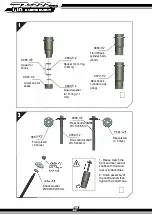
Page 47: ...d washer for 0 ring 1 1 mm C659X2 Rear centra 03 5 x55 5m C658X2 C669X2 Front shock cylinder body short C670X2 Rear shock cylinder body long D Front central shaft 03 5 x48mm Rear piston 4 holes 1 Plea...

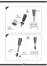
Page 48: ...k C653X4 Ball cup for shock C661 X4 C654X4 r dS06 As above picture shows fit the O ring into the recess of the adjusting ring and fit to shock absorber set to a gap of 4mm D Do not mark the central sh...

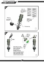
Page 49: ...mm r 1 I I I I I I I I C662 Shock button cap After adding 3 4 of the shock oil gently move the shaft up and down several times to eliminate air bubbles Then fill the shock body with shockoil until the...

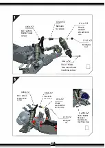
Page 50: ...3X22mm button head screw C624X2 fl C624X2 Ball stub for shock C114X2 Shock washer 03 207x0 5 mm X2 M3 Nyloc nut TM3X15mm Hex round head D machine screw C114X2 Shock washer03 2 07x0 5mm C118X2 M3 Nyloc...

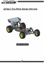
Page 51: ...I Stage 7 Tyre Wheel Sponge Rear wing Open Parts Bag G...

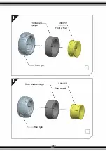
Page 52: ...Front whe C563X2 sponge Front wheel Front tyre D Rear wheel sponge C564X2 Rear wheel Rear tyre...

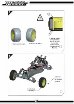
Page 53: ...Rear tyre completed Front tyre completed Front wheel complete r Jo _ 5 Once the wheels and tyres have been assembled run a small amount of thin CA glue around the rims D C673X2 M3 Flanged nyloc nut D...

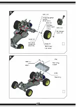
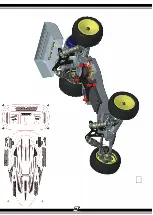
Page 54: ...C287X2 Hub carrier locating pin 02x11mm C671X2 washer 010x1 2mm C672X2 M2x5mm Button head screw C594X2 Rear wheel hub carrier C674X2 M4 Flanged nyloc nut D C556 Rear wing D...

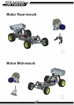
Page 55: ...Motor Rear mount D Motor Mid mount D...

Page 56: ...D...

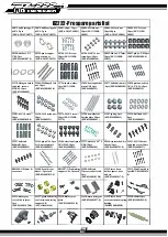
Page 57: ...0832 Pins cpl 5 7mm lOpcs SKU llOBS 30832 32877 ball end 06mm 6pcs SKU 249000302 33287 spring 4pcs SKU 9249000042 30997 pin cpl 5 6 lOpcs SKU 9249001008 0 32896 piston washer 0 2 6 06 5 0 5 lOpcs SKU...

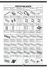
Page 58: ...countersunk hexagon countersunk SKU 9249001058 0 SKU 9249001060 0 screws lOpcs machine machine screws machine screws SKU 9249001062 0 screws SKU 924900106 SKU 9249001064 0 SKU 9249001065 0 3 0 33964...

Page 59: ...9249001192 0 BS34003 servo saver support lpcs BS34009 rear 33990 battery cover plate lPCS SKU 9249001187 0 33996 front shock tower carbon fiber lPCS SKU 9249001193 0 BS34004 battery cover support Ipcs...

Page 60: ...eck there are no binding parts the suspension parts should drop under their own weight with no shock absorbers mounted The car should also roll freely with very little effort 3 The batteries should be...

Page 61: ...to injury to yourself or others If in doubt fit fresh batteries 3 You will occasionally come across a fellow modeller with a radio controlled model Be sure to check that they are operating on a diffe...

Page 62: ......

Reviews: