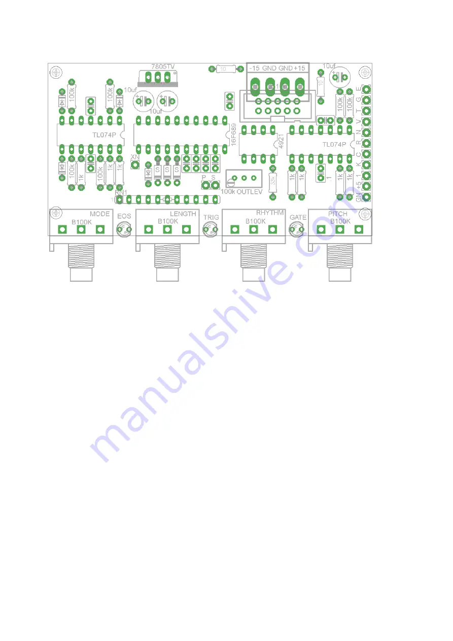
B.Wiring/PCB Information
Above is the PCB. It is 86mm x 45mm. The mounting holes are spaced 82mm x 37mm and the pots
are spaced 23mm apart.
The wiring pads should be connected as follows (starting from the corner of the PCB nearest the
panel):
GN -
Ground, connect the ground tab of one of the jacks
+5 -
+5V connect to the center tab of all the switches.
1
- Input for the "One" control, wire to the bottom tab of a toggleswitch.
K -
Input for the "Key" control, wire to the bottom tab of a toggleswitch.
C -
Input for the Clock input, wire to the Clock input jack
R -
Input for the Reset input, wire to the Reset input jack
N -
Input for the New input, wrire to the New pushbutton
V -
Output for the CV voltage, wire to the CV output jack
T -
Output for the trigger out, wire to the Trigger out jack
G -
Output for the gate out, wire to the Gate out jack
E -
End of Sequence output,
S
- Straight Rhythm input, wire to the bottom tab of a toggleswitch
P -
Portamento input, wire to the bottom tab of a toggle switch
XN - External new, wire to the New input jack


