WAM™ Wrist – Cable Maintenance Guide [email protected]
www.barrett.com
© 2008 Barrett Technology®, Inc.
Document: D1004, Version: AG.00
Page 7 of 13
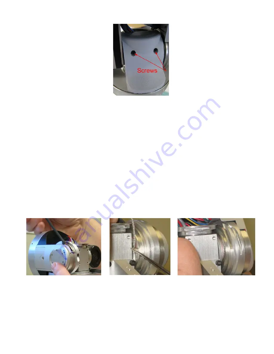
Figure 6 -- RTV rubber shroud.
□
1.
Rotate J6 to its far positive position. Using a 1/8” Hex Wrench, remove the worm on the section of the vertical steps with
the smaller diameter (see Figure 7). Set it aside (keeping it in a place where it will not be lost).
□
2.
Rotate J6 to its far negative position. Remove the worm on the section of the vertical steps with the larger diameter. Set it
aside separately from the other worm, taking care to note which side each worm was seated, as you will need to replace it
on the same side when done.
□
3.
The Level 2 cable (B1217) must be pre-installed between the horizontal and vertical pulleys before any other cables are
installed, because the gap between the Level 2 horizontal pulley and Level 2 vertical pulley is too small for the brass
termination on the cable to fit through. The bottom 3
rd
stage pulley and 2 upper horizontal differential pulleys are fixed to
each other. Manually turn the bottom 3
rd
stage pulley until the 2 upper horizontal pulleys look roughly as shown in Figure
9. Insert one end of the Level 2 cable (B1217) BACKWARDS into the Level 2 horizontal pulley anchor. Rotate the
bottom 3
rd
stage pulley counter-clockwise approximately ½ turn. The cable should now be threaded through the small gap
between the Level 2 horizontal and vertical pulleys. Remove the brass termination from the horizontal pulley and leave
both ends of the cable unconnected.
□
4.
Get a Level 1 cable (B1216) and insert one end of the cable into the vertical anchor on the level 1 wrist differential (see
Figure 8) and thread the cable through the gap between the steps (see Figure 9). (All other differential cables are installed
similarly, so use Figure 8 and Figure 9 as reference points for the other circuits.)
□
5.
Cross the cable onto the smallest step of the upper horizontal differential level. Rotate the Level 1 horizontal pulley as
required (by rotating the 3
rd
stage bottom pulley) and insert the termination into the anchor, then rotate the bottom 3
rd
stage
pulley by hand to tighten the cable.
Figure 7 – Removing the Worm
Figure 8 – Anchoring the Level 1
Cable
Figure 9 – Threading the Level 1 Cable
□
6.
Put one end of the pre-threaded Level 2 cable (B1217) in the anchor in the larger horizontal step in the differential top
(Level 2)
□
7.
Cross over to the Level 2 vertical step, rotate the vertical step (the tensioner worm is not yet installed) as necessary to allow
the second termination to be inserted into the anchor on the second step. Then, rotate it back to tighten the cables.


