8
SECTION: D START-UP OPERATION
D-1) Check Voltage and Phase:
Before operating pump, compare the voltage and phase
information stamped on the pump identi
fi
cation plate to the
available power.
D-2) Check Pump Rotation:
Before putting pump into service for the
fi
rst time, the motor
rotation must be checked. Improper motor rotation can
result in poor pump performance and can damage the motor
and/or pump. To check the rotation, suspend the pump
freely, momentarily apply power and observe the “kickback”.
“Kickback” should always be in a counter-clockwise direction
as viewed from the top of the pump motor housing.
D-2.1) Incorrect Rotation for Single-Phase Pumps:
In the unlikely event that the rotation is incorrect for a single
phase pump, contact a Barnes Pumps Service Center.
D-3) Start-Up Report:
Included at the end of this manual is a start-up report form,
this form is to be completed as applicord. Return one copy to
Barnes Pumps, Inc. and store a copy in the control panel or
with the pump manual if no control panel is used. It is important
to record this data at initial start-up since it will be useful to
refer to should servicing the pump be required in the future.
D-3.1) Identi
fi
cation Plate:
Record the numbers from the pump identi
fi
cation plate on
both START-UP REPORT provided at the end of the manual
for future reference.
D-3.2) Insulation Test:
Before the pump is put into service, an insulation (megger)
test should be performed on the motor. The resistance values
(ohms) as well as the voltage (volts) and current (amps)
should be recorded on the start-up report.
D-3.3) Pump-Down Test:
After the pump has been properly wired and lowered into the
basin, sump or lift station, it is advisable to check the system
by
fi
lling with liquid and allowing the pump to operate through
its pumping cycle. The time needed to empty the system, or
pump-down time along with the volume of water, should be
recorded on the start-up report.
SECTION E: PREVENTATIVE MAINTENANCE
As the motor is oil
fi
lled, no lubrication or other maintenance
is required, and generally Barnes Pumps will give very
reliable service and can be expected to operate for years on
normal sewage pumping without failing. However as with any
mechanical piece of equipment a preventive maintenance
program is recommended and suggested to include the
following checks:
1) Inspect motor chamber for oil level and contamination
and repair as required per section F-1.
2) Inspect impeller and body for excessive build-up or
clogging and repair as required per section F-2.
3) Inspect motor and bearings and replace as required
per section F-3.
4) Inspect seal for wear or leakage and repair as required
per section F-4.
SECTION F: SERVICE AND REPAIR
NOTE:
All item numbers in ( ) refer to Figures 15 and 16.
F-1) Lubrication:
Anytime the pump is removed from operation, the cooling oil
in the motor housing (6) should be checked visually for oil
level and contamination.
F-1.1) Checking Oil:
Motor Housing -
To check oil, set unit upright. Remove pipe
plug (39) from motor housing (6). With a
fl
ashlight, visually
inspect the oil in the motor housing (6) to make sure it is
clean and clear, light amber in color and free from suspended
particles. Milky white oil indicates the presence of water. Oil
level should be just above the motor when pump is in vertical
position.
F-1.2) Testing Oil:
1.)
Place pump on it’s side, remove pipe plug (39), from
motor housing (6) and drain oil into a clean, dry container.
2.)
Check oil for contamination using an oil tester with a
range to 30 Kilovolts breakdown.
3.)
If oil is found to be clean and uncontaminated
(measuring above 15 KV. breakdown), re
fi
ll the motor
housing as per section F-1.4.
4.)
If oil is found to be dirty or contaminated (or measures
below 15 KV. breakdown), the pump must be carefully
inspected for leaks at the shaft seal (28), cord
assembly (16), square ring (27) and pipe plug (39),
before
re
fi
lling with oil. To locate the leak, perform a
pressure test as per section F-1.3. After leak is repaired,
dispose of old oil properly, and re
fi
ll with new oil as per
section
F-1.4.
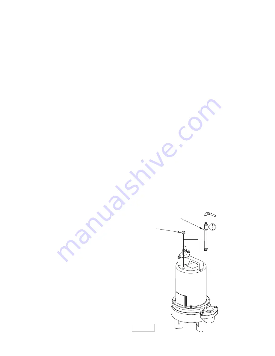
F-1.3) Pressure Test:
Pumps that have been disassembled, Motor Housing -
If the
pump has been disassembled, the oil should be drained before
a pressure test, as described in section F-1.1. Remove pipe
plug (39) from motor housing (6). Apply pipe sealant to pressure
gauge assembly and tighten into hole (See Figure 4).
FIGURE 4
Remove Plug
Pressure Gauge Assy
(See Parts List)
10 PSI
AIR


