


8
1) Inspect motor chamber for oil level and contamination and
repair as required per section F-1.
2) Inspect impeller and body for excessive build-up or clogging
and repair as required per section F-2.
3) Inspect motor and bearings and replace as required per
section F-3.
4) Inspect seal for wear or leakage and repair as required per
section F-4.
SECTION F: SERVICE AND REPAIR
NOTE: All item numbers in ( ) refer to Figures 11 & 12.
F-1) Lubrication:
Anytime the pump is removed from operation, the cooling oil
in the motor housing (5) should be checked visually for oil
level and contamination.
F-1.1) Checking Oil:
Motor Housing -
To check oil, set unit upright. Remove pipe
plug (19) from housing (5). With a flashlight, visually inspect
the oil in the motor housing (5) to make sure it is clean and
clear, light amber in color and free from suspended particles.
Milky white oil indicates the presence of water. Oil level should
be just above the motor when pump is in a vertical position.
F-1.2) Testing Oil:
1. Place pump on it’s side, remove pipe plug (19), from motor
housing (5) and drain oil into a clean, dry container.
2. Check oil for contamination using an oil tester with a range
to 30 Kilovolts breakdown.
3. If oil is found to be clean and uncontaminated (measure
above 15 KV. breakdown), refill the motor housing as per
section F-1.4.
4. If oil is found to be dirty or contaminated (or measures
below 15 KV. breakdown), the the pump must be carefully
inspected for leaks at the shaft seal (31), cable assemblies
(30) and (32 if used), square ring (8) and pipe plug (19)
before refilling with oil. To locate the leak, perform
a pressure test as per section F-1.3. After leak is repaired,
refill with new oil as per section F-1.4.
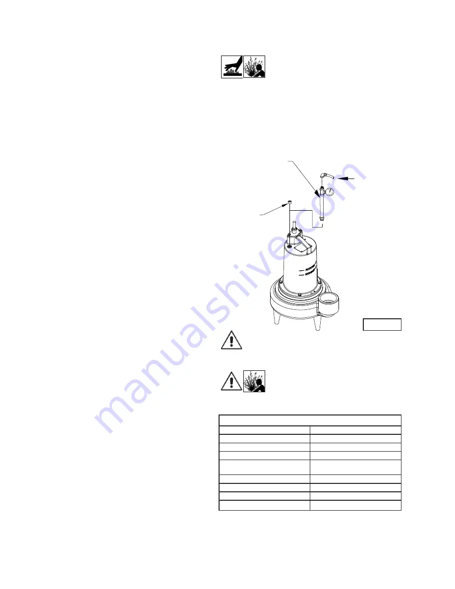
F-1.3) Pressure Test:
Pumps that have had the oil drained from the Motor
Housing -
Apply pipe sealant to pressure gauge assembly
and tighten into pipe plug hole (See Figure 2). Pressurize
motor housing to 10 P.S.I. Use soap solution around the
sealed areas and inspect joints for “air bubbles”. If, after
five minutes, the pressure is still holding constant, and no
“bubbles” are observed, slowly bleed the pressure and
remove the gauge assembly. Replace oil as described in
section F-1.4. If the pressure does not hold, then the leak
must be located and repaired.
Pumps that have NOT had the oil drained from the Motor
Housing -
The pressure test may be done with the oil at its
normal level. Remove pipe plug (19) from motor housing (5).
Apply pipe sealant to pressure gauge assembly and tighten
into hole (see Figure 2). Pressurize motor housing to 10 P.S.I.
Use soap solution around the sealed areas above the oil level
and inspect joints for “air bubbles”. For sealed areas below
the oil level, leaks will seep oil.
If, after five minutes, the pressure is still holding constant,
and no “bubbles”/oil seepage is observed, slowly bleed the
pressure and remove the gauge assembly. If the pressure
does not hold, then the leak must be located and repaired.
CAUTION ! - Pressure builds up extremely
fast, increase pressure by “TAPPING” air
nozzle. Too much pressure will damage
seal. DO NOT exceed 10 P.S.I.
F-1.4) Replacing Oil:
Motor Housing-
Set unit upright and refill with new cooling
oil as per Table 1 (see parts list for amount). Fill to just above
motor as an air space must remain in the top of the motor
housing to compensate for oil expansion (see Figure 2, 11 or
12). Apply pipe thread compound to threads of pipe plug (19)
then assemble to motor housing (5).
IMPORTANT! - For single phase units, oil level
should be below capacitor.
WARNING ! - DO NOT overfill oil.
Overfilling of motor housing with oil
can create excessive and dangerous
hydraulic pressure which can destroy the
pump and create a hazard. Overfilling oil
voids warranty.
TABLE 1 - COOLING OIL - Dielectric
SUPPLIER
GRADE
Sohio / Standard
SE 40, Energol HL22 or HL32
Shell
Turbo Oil 32
Texaco
Rando HD32, 522
Sun Petroleum
Supar 110, Sunvis 816WR, 911
or 916
Mobile
D.T.E. Oil Light or Rubrex 200
G&G
Circu Oil 22
Allegheny Petroleum
Altrapar 22
Woco
Premium 100
F-2) Impeller and Volute Service:
F-2.1) Disassembly and Inspection:
To clean out volute (24) or replace impeller (29), disconnect
power, remove screws (12), and lockwashers (11), vertically
REMOVE PLUG
PRESSURE GAUGE ASSY
(SEE PARTS LIST)
10 PSI AIR
FIGURE 2
Summary of Contents for 3SEH-L
Page 13: ...13 FIGURE 10...
Page 20: ...20 Notes...


