


Package content
a Annuncicom
1000
b Power
supply
c Serial
cable
d
Screw block terminals (4 x 8 pin, 6 x 3 pin)
e
Label stickers for screw block terminals
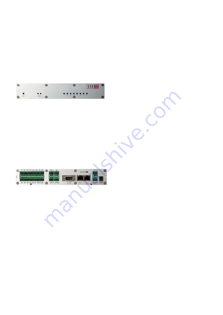
Front view
1
2
3
1 Reset button (Press this button shortly to reset the
device. If you press it until the red light flashes (about 5
seconds) the device will be reset to factory defaults.
2 Green and red LED for status display
3 Green LED (1...8) for I/O status display
Rear view
A B* C D E
F G* H I J K L M N
A Relay outputs 1..4 (1/2:R01, 3/4:R02, 5/6:R03,7/8:R04)
B Inputs 1..4 (1:IN1+,2:-, 3:IN2+, 4:-, 5:IN3+, 6:-, 7:IN4+, 8:-)
* WARNING: An input voltage on the “+” pin greater
than 5 VDC can destroy the device!
The “-“ pin is connected to the power supply “–“ pin!
C Left audio output (symmetric: cold:1, shield:2, hot:3)
Shield pin is connected to the power supply “–“ pin!
D Left audio input (symmetric: cold:1, shield:2, hot:3)
Shield pin is connected to the power supply “–“ pin!
E RS-485 bus (B:1, reference:2, A:3). The reference pin is
connected via 100 Ohm to the power supply “–“ pin!
F Relay outputs 5…8 (R05:1/2, R06:3/4, R07:5/6, R08:7/8)
G Inputs 5…8 & Fault Relay (1:IN1+, 2:-, 3:IN2+, 4:IN3+,
5:-, 6:IN4+, 7/8 Fault Relay [Normally Closed])
* WARNING: An input voltage on the “+” pin greater
than 5 VDC can destroy the device!
The “-“ pin is connected to the power supply “–“ pin!
H Right audio output (symmetric: cold:1, shield:2, hot:3)
Shield pin is connected to the power supply “–“ pin!
Rear view (continued)
I Right audio input or Microphone input (symmetric:
cold:1, shield:2, hot:3 / Mic. power configurable)
Shield pin is connected to the power supply “–“ pin!
J RS-232 serial port (DSub9 male)
K ETH1 RJ45 for LAN 10/100 Half/Full duplex
L ETH2 RJ45 (NOT supported)
M Power (1: +24..48 VDC, 2/3: power supply minus)
E Power (center: +24..48 VDC, ring: power supply minus)
Installation
STEP 1
Plug a standard (straight) network cable (not included) into
the network port (K) of the Annuncicom 1000 and the
other end into your hub or switch. You can also use a
crossover network cable (not included) for a direct
connection to your PC.
STEP 2
Connect at least the left output (C, &H for stereo) to the
amplifier or mixer input(s) and adjust the volume for
speaker(s) or a headphone. Get a pen and paper ready to
write down the IP address that will be announced in step 4.
STEP 3
Plug the power supply (b) into the
power jack ( E ) of the
device and the other end into the power outlet of the wall.
STEP 4
The Annuncicom 1000 will now search for a DHCP server
to get an IP address and announce it over the audio
outputs.
Example:192.168.0.12 (Voice: one nine two…)
Make sure you write this IP address down.
Your Annuncicom 1000 is now ready to start working.
We recommend, however, that you set a Static IP address.
See next pages on how to do this or download the user
manual from www.barix.com.
Troubleshooting:
If no DHCP server is found then our IPzator function will
search the network for a free IP address (this could take up
to 5 minutes).
If the IP address is not announced check if the green LED
(right LED on top of network port A) is lit. If it stays dark
check your network cabling. If the front LEDs (3) stay dark
check the power cabling (step 3).
If it still fails than revert the device to factory defaults by
pressing the Reset button (1) for about 5 seconds while the
Annuncicom is powered and repeat the above steps.


