


2 0 4
Insta
ll
at
i
on
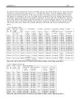
14.1
P
r
odu
c
t
r
a
t
i
ng t
a
b
l
e
Output po w er
A t
5 0 0 V
Max cont
i
nuous
Current (A MPS)
Max
i
mum f
i
e
l
d
output current
(D C A mps)
Max
i
mum
A ux
ili
ary
Fuse rat
i
ngs
Coo
li
ng a
i
r
f
l
o w and
d
i
ss
i
pat
i
on
Mode
l
PL 2 Q
PLX 4 Q
A t
4 6 0 V
K w HP
HP
Input
A C
Output
D C
Standard
Opt
i
on
Ma
i
n
fuses
max
I
2
t
A mp I
2
t
L
i
ne
reac
-tor
type
cfm
w atts
PL/X 5
5
7
7.5
1 0
1 2
8
6 0 0
2 0
3 6 5
LR4 8
1 7
4 5
PL/X 1 0
1 0
1 3
1 5
2 0
2 4
8
6 0 0
2 0
3 6 5
LR4 8
1 7
8 0
PL/X 1 5
1 5
2 0
2 0
3 0
3 6
8
6 0 0
2 0
3 6 5
LR4 8
1 7
1 2 0
PL/X 2 0
2 0
2 7
3 0
4 0
5 1
8
5 0 0 0
2 0
3 6 5
LR4 8
1 7
1 2 0
PL/X 3 0
3 0
4 0
4 0
6 0
7 2
8
5 0 0 0
2 0
3 6 5
LR1 2 0
3 5
2 0 0
PL/X 4 0
4 0
5 3
6 0
8 0
9 9
8
5 0 0 0
2 0
3 6 5
LR1 2 0
3 5
3 0 0
PL/X 5 0
5 0
6 7
7 5
1 0 0
1 2 3
8
1 1 8 5 0
2 0
3 6 5
LR1 2 0
3 5
3 2 0
PL/X 6 5
6 5
9 0
1 0 0
1 2 4
1 5 5
1 6
6 0 0 0 0
2 0
3 6 5
LR2 7 0
6 0
3 5 0
PL/X 8 5
8 5
1 1 5
1 2 5
1 6 4
2 0 5
1 6
6 0 0 0 0
2 0
3 6 5
LR2 7 0
6 0
4 7 5
PL/X 1 1 5
1 1 5
1 5 5
1 6 0
2 1 6
2 7 0
1 6
1 2 8 0 0 0
2 0
3 6 5
LR2 7 0
6 0
6 5 0
PL/X 1 4 5
1 4 5
1 9 0
2 0 0
2 7 0
3 3 0
1 6
1 2 8 0 0 0
2 0
3 6 5
LR3 3 0
6 0
8 5 0
PL/X 1 8 5
1 8 5
2 5 0
2 7 0
3 5 0
4 3 0
3 2
5 0
2 4 0 0 0 0
5 0
5 0 0 0
LR4 3 0
1 8 0
1 0 0 0
PL/X 2 2 5
2 2 5
3 0 0
3 3 0
4 3 5
5 3 0
3 2
5 0
2 4 0 0 0 0
5 0
5 0 0 0
LR5 3 0
1 8 0
1 3 0 0
PL 2 6 5
2 6 5
3 6 0
4 0 0
5 2 0
6 3 0
3 2
5 0
3 0 6 0 0 0
5 0
5 0 0 0
LR6 3 0
1 8 0
1 6 0 0
P
l
ea
s
e
a
l
so
r
e
f
e
r
to
Pa
r
t 3
PL
/X 275-980 fo
r
e
xt
r
a
d
e
t
a
il
s of f
r
a
m
e
4
a
nd 5 h
i
gh pow
e
r
d
ri
v
e
s.
Notes
1) On
l
y use UL fuses for
i
nsta
ll
at
i
ons comp
l
y
i
ng w
i
th UL codes.
2) 2 Q mode
l
s PL/5/1 0/1 5/2 0/3 0/4 0/5 0/1 4 5/2 2 5 ha ve a regenerat
i
ve stopp
i
ng capab
ili
ty.
3) The PL/X 1 8 5/2 2 5/2 6 5 requ
i
res 3 aux
ili
ary fuses, (max rat
i
ngs 5 0 A , I
2
t 5 0 0 0), standard type C H 0 0 8 5 0 A .
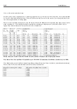
4) The standard aux
ili
ary fuses
i
n the above tab
l
e are chosen for the I
2
t rat
i
ng. W hen se
l
ect
i
ng a
l
ternat
i
ve
types the fuse current rat
i
ng must be at
l
east 1.2 5 X the f
i
e
l
d current rat
i
ng of the motor. The I
2
t rat
i
ng of
the fuse must not exceed the f
i
gure
i
n the tab
l
e.
5) P
l
ease cons
i
der the tota
l
component d
i
ss
i
pat
i
on w
i
th
i
n the enc
l
osure w hen ca
l
cu
l
at
i
ng the requ
i
red a
i
r
throughput. Th
i
s
i
nc
l
udes the fuses,
li
ne reactors and other sources of d
i
ss
i
pat
i
on. See 1 4.8 L
ne reactor and
ngs for component d
i
ss
i
pat
i
on rat
i
ngs.
6) 3 5 Cub
i
c feet per m
i
nute
i
s approx
i
mate
l
y equ
i
va
l
ent to 1 cub
i
c metre per m
i
nute.
1 8 0 Cub
i
c feet per m
i
nute
i
s approx
i
mate
l
y equ
i
va
l
ent to 6 cub
i
c metres per m
i
nute.
7) The output po w er rat
i
ng sho w n
i
s at the 1 0 0 % rat
i
ng of the dr
i
ve and
i
s the po w er ava
il
ab
l
e at the shaft
for a typ
i
ca
l
motor. The actua
l
po w er ava
il
ab
l
e w
ill
depend on the eff
i
c
i
ency of the motor.
8) The h
i
gh po w er f
i
e
l
d output opt
i
on
i
s an extra cost fac
ili
ty and needs to be spec
i
f
i
ed at the t
i
me of order.
14.2
P
r
odu
c
t
r
a
t
i
ng
l
a
b
e
l
s
The product rat
i
ng
l
abe
l
s are
l
ocated on the un
i
t under the upper end cap. The product ser
i
a
l
number
i
s
un
i
que and can be used by the manufacturer to
i
dent
i
fy a
ll
rat
i
ngs of the un
i
t. The po w er rat
i
ngs and mode
l
type are a
l
so found here, a
l
ong w
i
th any product standard
l
abe
l
s app
li
cab
l
e to the un
i
t.
14.3 S
e
m
i
c
ondu
c
to
r
fus
e
r
a
t
i
ngs
WA
R
N
I
NG. A
ll
un
i
ts must b
e
p
r
ot
ec
t
e
d by
c
o
rr
ec
t
l
y
r
a
t
e
d s
e
m
i
-
c
ondu
c
to
r
fus
e
s. F
a
il
u
r
e
to do so w
ill
i
nv
a
li
d
a
t
e
w
a
rr
a
nty.
In genera
l
the
i
nput A C supp
l
y current per phase
i
s 0.8 t
i
mes the D C output current, and the fuse rat
i
ng
shou
l
d be approx. 1.2 5 t
i
mes the
i
nput A C current. The fuses spec
i
f
i
ed
i
n th
i
s tab
l
e have been rated to
i
nc
l
ude the 1 5 0 % over
l
oad capab
ili
ty and operate up to 5 0 C amb
i
ent at the max
i
mum dr
i
ve rat
i
ng. To se
l
ect
a fuse at other rat
i
ngs (E.g. w hen us
i
ng a motor rated at a
l
o w er po w er than the dr
i
ve un
i
t or operat
i
ng at a
reduced max
i
mum current
li
m
i
t sett
i
ng) se
l
ect a fuse w
i
th a current rat
i
ng c
l
osest to the armature current and
w
i
th an I
2
t rat
i
ng
l
ess than the max
i
mum sho w n
i
n the tab
l
e. If a D C fuse
i
s f
i
tted
i
n ser
i
es w
i
th the armature
i
t must be a D C rated sem
i
conductor type w
i
th current rat
i
ng 1.2 t
i
mes the motor fu
ll
l
oad current, D C
vo
l
tage rat
i
ng su
i
tab
l
e for the max
i
mum armature vo
l
tage and w
i
th an I
2
t rat
i
ng
l
ess than the max
i
mum
sho w n
i
n the tab
l
e. See 14.3.3 D C sem
Summary of Contents for PLX
Page 2: ...2 Contents ...
Page 202: ......