© Copyright 2005
Manual No.:
2100-461
Supersedes:Date:
06-20-05
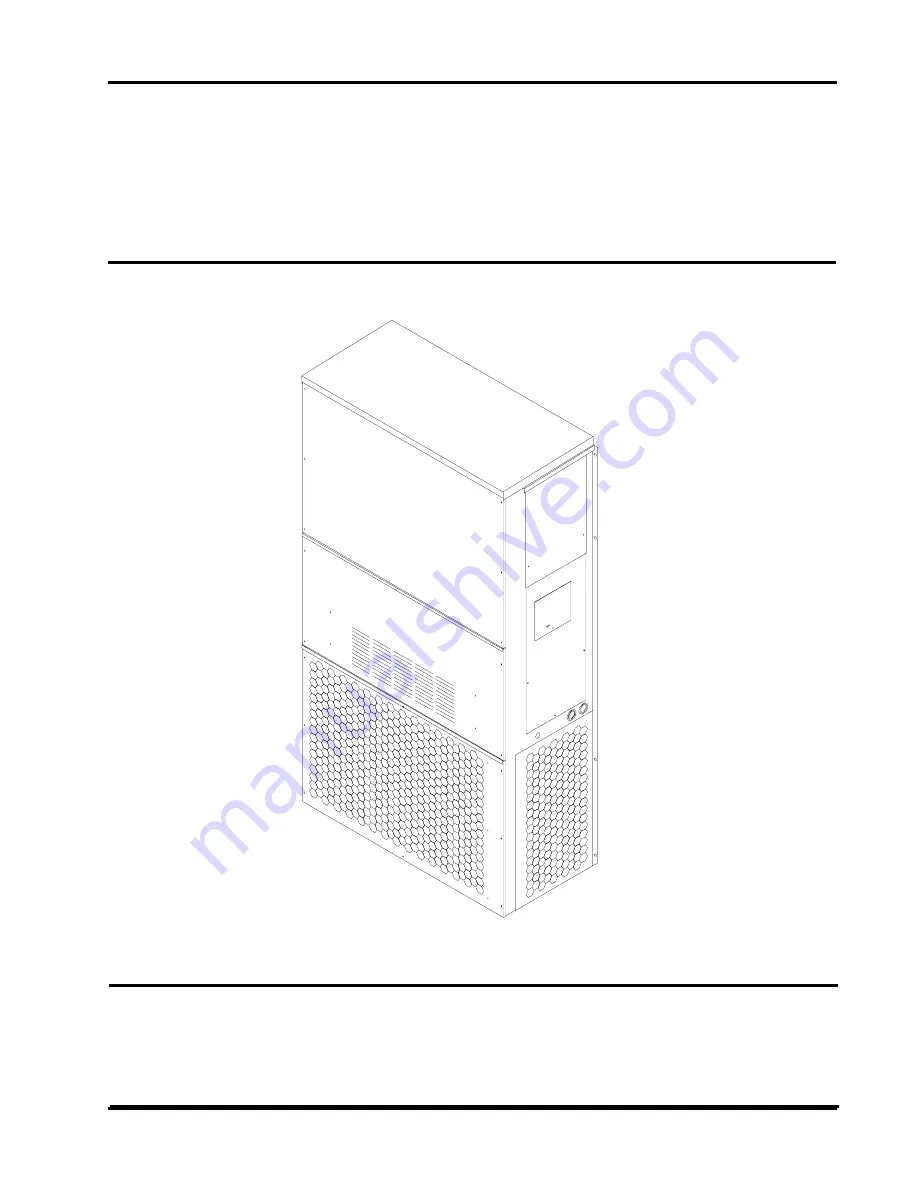
INSTALLATIONINSTRUCTIONS
Models:
YA302YA372
WALL MOUNTEDPACKAGEDAIR CONDITIONER
MIS-383
Page 1: ... Copyright 2005 Manual No 2100 461 Supersedes Date 06 20 05 INSTALLATION INSTRUCTIONS Models YA302 YA372 WALL MOUNTED PACKAGED AIR CONDITIONER MIS 383 ...
Page 2: ...Voltage Wiring 12 Figure 9 Fan Blade Setting 15 Tables Table 1 Electrical Specifications 2 Table 2 Dimensions of Basic Unit 3 Table 3 Electric Heat Table 4 Table 4 Operating Voltage Range 7 Table 5 Thermostat Wire Size 7 Table 6 Wall Thermostat and Subbase Combinations 7 Table 7 Fan Blade Dimensions 15 Table 8 Suction Line Temperatures 15 Table 9 Indoor Blower Performance 15 Table 10 CFM and ESP 1...
Page 3: ... Manual D Winter and Summer Air Conditioning and Equipment Selection FOR MORE INFORMATION CONTACT THESE PUBLISHERS ACCA Air Conditioning Contractors of America 1712 New Hampshire Avenue NW Washington DC 20009 Telephone 202 483 9370 Fax 202 234 4721 ANSI American National Standards Institute 11 West Street 13th Floor New York NY 10036 Telephone 212 642 4900 Fax 212 302 1286 ASHRAE American Society ...
Page 4: ... y t i c a p m A 1 m u m i x a M l a n r e t x E r o e s u F t k C r e k a e r B 2 d l e i F r e w o P e r i W e z i S 2 d n u o r G e r i W e z i S 3 m u m i n i M t i u c r i C y t i c a p m A 1 m u m i x a M l a n r e t x E e s u F t k C r o r e k a e r B 2 r e w o P d l e i F e z i S e r i W 2 d n u o r G e z i S e r i W T K C A T K C B T K C A T K C B T K C A T K C B T K C A T K C B Z 0 A 2 0...
Page 5: ...W h t p e D D t h g i e H H y l p p u S n r u t e R E F G I J K L M N O P Q R S T A B C B 2 0 3 A Y 2 7 3 A Y 0 2 8 3 5 2 1 7 1 3 6 5 0 7 8 8 7 8 8 7 2 8 8 3 1 8 8 7 2 0 0 0 4 0 5 8 1 5 7 5 2 3 9 7 1 5 7 6 2 5 7 8 2 5 2 9 2 0 0 7 2 5 7 2 9 1 9 3 5 7 2 2 4 1 9 9 1 4 0 0 2 1 0 0 5 FRONT VIEW BACK VIEW SIDE VIEW ...
Page 6: ...mmended guide they do not supersede any national and or local codes in any way Authorities having jurisdiction should be consulted before the installation is made See Page 1 for information on codes and standards Size of unit for a proposed installation should be based on heat loss calculation made according to methods of Air Conditioning Contractors of America ACCA The air duct should be installe...
Page 7: ...y and return must be properly sized for the design air flow requirement of the equipment Air Conditioning Contractors of America ACCA is an excellent guide to proper sizing All duct work or portions thereof not in the conditioned space should be properly insulated in order to both conserve energy and prevent condensation or moisture damage Refer to Table 11 for maximum static pressure available fo...
Page 8: ...igure 6 WIRING MAIN POWER Refer to the unit rating plate for wire sizing information and maximum fuse or HACR Type circuit breaker size Each outdoor unit is marked with a Minimum Circuit Ampacity This means that the field wiring used must be sized to carry that amount of current Depending on the installed KW of electric heat there may be two field power circuits required If this is the case the un...
Page 9: ...d 7 c i n o r t c e l E 3 4 0 3 0 4 8 0 0 2 M C l o o c e g a t s 1 t a e h e g a t s 1 n o o t u a n a F l o o c f f o t a e h m e t s y S WIRING LOW VOLTAGE WIRING 230 208V 1 phase and 3 phase equipment dual primary voltage transformers All equipment leaves the factory wired on 240V tap For 208V operation reconnect from 240V to 208V tap The acceptable operating voltage range for the 240 and 208V...
Page 10: ...nual 2100 461 Page 8 FIGURE 3 MOUNTINGINSTRUCTIONS NOTE It is recommended that a bead of silicone caulking be placed behind the side mounting flanges and under the top flashing at the time of installation ...
Page 11: ...61 Page 9 FIGURE 4 WALL MOUNTINGINSTRUCTIONS FIGURE 5 WALL MOUNTINGINSTRUCTIONS MIS 548 SEE FIGURE 3 MOUNTING INSTRUCTIONS SEE UNIT DIMENSIONS FIGURE 1 FOR ACTUAL DIMENSIONS SEE FIGURE 1 FOR DUCT DIMENSIONS MIS 549 ...
Page 12: ...Manual 2100 461 Page 10 MIS 550 FIGURE 6 COMMONWALL MOUNTINGINSTALLATIONS ...
Page 13: ...NCE MIS 277 WARNING WARNING A minimum of 1 4 inch clearance must be maintained between the supply air duct and combustible materials This is required for the first 3 feet of ducting It is important to insure that the 1 4 inch minimum spacing is maintained at all points Failure to do this could result in overheating the combustible material and may result in fire ...
Page 14: ...Manual 2100 461 Page 12 FIGURE 8 LOW VOLTAGE WIRING ...
Page 15: ...essure drops and discharge pressure rises when the compressor is energized Reverse rotation also results in an elevated sound level over that with correct rotations as well as substantially reduced current draw compared to tabulated values START UP PHASE MONITOR All units with three phase compressors are equipped with a 3 phase line monitor to prevent compressor damage due to phase reversal The ph...
Page 16: ...TROL MODULE The compressor control module is optional on the models covered by this manual The compressor control is an anti short cycle lockout timer with high and low pressure switch monitoring and alarm relay output Adjustable Delay On Make And Break Timer On initial power up or any time power is interrupted to the unit the delay on make period begins which will be 2 minutes plus 10 of the dela...
Page 17: ... o C y r D l i o C t e W l i o C y r D l i o C t e W 0 5 9 3 1 5 1 3 1 0 5 9 5 3 9 1 0 4 3 1 0 7 2 1 0 3 9 5 1 9 2 5 8 2 1 0 9 1 1 0 1 9 5 8 8 3 5 0 2 1 0 0 1 1 5 5 8 0 3 8 4 0 1 1 1 0 0 0 1 0 0 8 5 5 7 5 5 0 0 1 0 7 8 TABLE 11 MAXIMUM ESP OF OPERATION ELECTRIC HEAT ONLY l e d o M t e l t u O t n o r F t e l t u O p o T d e e p S w o L d e e p S h g i H d e e p S w o L d e e p S h g i H d e e p S ...
Page 18: ... 8 7 4 4 2 9 7 8 5 2 0 8 5 7 2 1 8 2 9 2 3 8 8 0 3 4 8 7 2 3 5 8 5 4 3 B D g e d 0 8 B W g e d 7 6 e d i S w o L e d i S h g i H 0 8 0 2 2 1 8 5 3 2 3 8 0 5 2 5 8 5 6 2 6 8 2 8 2 7 8 9 9 2 9 8 6 1 3 0 9 5 3 3 1 9 4 5 3 B D g e d 5 8 B W g e d 2 7 e d i S w o L e d i S h g i H 3 8 8 2 2 4 8 3 4 2 6 8 9 5 2 8 8 4 7 2 9 8 2 9 2 0 9 9 0 3 2 9 7 2 3 3 9 7 4 3 4 9 6 6 3 2 7 3 A Y B D g e d 5 7 B W g e d...
Page 19: ... n o C t n e i b m A w o L X X X A 6 1 A M C l o r t n o C e r u s s e r P w o L X X X X A 8 1 A M C C P L C A L X X X 5 1 C M C t i K t r a t S X 5 0 A 3 0 A W H E e g a k c a P r e t a e H 1 X 8 0 A 3 0 A W H E e g a k c a P r e t a e H 1 X 0 1 A 3 0 A W H E e g a k c a P r e t a e H 1 X 5 1 A 3 0 A W H E e g a k c a P r e t a e H 1 X 6 0 B 3 0 A W H E e g a k c a P r e t a e H 1 X X 9 0 B 3 0 A...