Bard WH303 Installation Instructions Manual Download Page 4

Manual 2100-489
Page

4 of 26

WALL MOUNT GENERAL INFORMATION

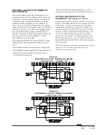
HEAT PUMP WALL MOUNT MODEL NOMENCLATURE

WH

36

3

A

10

X

X

X

X

X

A

VOLTS & PHASE

A - 230/208/60/1
B - 230/208/60/3
C - 460/60/3

MODEL NUMBER

REVISIONS

CAPACITY

30 -  2

½

 Ton

36 -  3 Ton

KW

VENTILATION OPTIONS

X - Barometric Fresh Air Damper (Standard)
B - Blank-off Plate
M - Motorized Fresh Air Damper
V - Commercial Room Ventilator - Motorized with Exhaust
E - Economizer (Internal - Fully Modulating with Exhaust
R - Energy Recovery Ventilator - with Exhaust

FILTER OPTIONS

X - 1-Inch Throwaway (Standard)
W - 1-Inch Washable
P - 2-Inch Pleated

COLOR OPTIONS

X - Beige (Standard)
1 - White
2 - Mesa Brown
4 - Buckeye Gray
5 - Desert Brown
8 - Dark Bronze

CONTROL

MODULES

COIL OPTIONS
 

X - Standard

 1 - Phenolic Coated Evaporator
 2 - Phenolic Coated Condenser
 3 - Phenolic Coated Evaporator

and Condenser

OUTLET OPTIONS

 X - Front (Standard)
 T - Top on WH30 and WH36

Models

NOTE:  For 0 KW and circuit breakers (230/208 Volt) or pull disconnects (460 Volt) applications, insert 0Z in the KW field of model number.

SHIPPING DAMAGE

Upon receipt of equipment, the carton should be checked
for external signs of shipping damage.  If damage is
found, the receiving party must contact the last carrier
immediately, preferably in writing, requesting inspection
by the carrier’s agent.

GENERAL

The equipment covered in this manual is to be installed
by trained, experienced service and installation
technicians.

The refrigerant system is completely assembled and
charged.  All internal wiring is complete.

The unit is designed for use with or without duct work.
Flanges are provided for attaching the supply and return
ducts.

These instructions explain the recommended method to
install the air cooled self-contained unit and the
electrical wiring connections to the unit.

These instructions and any instructions packaged with
any separate equipment required to make up the entire
heat pump system should be carefully read before
beginning the installation.  Note particularly “Starting
Procedure” and any tags and/or labels attached to the
equipment.

While these instructions are intended as a general
recommended guide, they do not supersede any national
and/or local codes in any way.  Authorities having
jurisdiction should be consulted before the installation is
made.  See Page 3 for information on codes and
standards.

Size of unit for a proposed installation should be based
on heat loss calculations made according to methods of
Air Conditioning Contractors of America (ACCA).  The
air duct should be installed in accordance with the
Standards of the National Fire Protection Association for
the Installation of Air Conditioning and Ventilating
Systems of Other Than Residence Type, NFPA No. 90A,
and Residence Type Warm Air Heating and Air
Conditioning Systems, NFPA No. 90B.  Where local
regulations are at a variance with instructions, installer
should adhere to local codes.

DUCT WORK

Any heat pump is more critical of proper operating
charge and an adequate duct system than a straight air
conditioning unit.  All duct work, supply and return,
must be properly sized for the design airflow
requirement of the equipment.  Air Conditioning
Contractors of America (ACCA) is an excellent guide to
proper sizing.  All duct work or portions thereof not in
the conditioned space should be properly insulated in
order to both conserve energy and prevent condensation
or moisture damage.

Summary of Contents for WH303

Page 1: ...els WH303 WH363 WALL MOUNTED PACKAGED HEAT PUMP INSTALLATION INSTRUCTIONS Manual No 2100 489 Supersedes NEW File Volume III Tab 17 Date 01 18 08 Bard Manufacturing Company Inc Bryan Ohio 43506 Since 1...

Page 2: ...6 Figure 2 Fresh Air Damper Assembly 8 Figure 3 Mounting Instructions 10 Figure 4 Electric Heat Clearance 11 Figure 5 Attaching Top Outlet to Unit 12 Figure 6 Top Outlet Model Mounted 12 Figure 7 Wall...

Page 3: ...er and Summer Air Conditioning Duct Design for Residential ACCA Manual D Winter and Summer Air Conditioning and Equipment Selection FOR MORE INFORMATION CONTACT THESE PUBLISHERS ACCA Air Conditioning...

Page 4: ...supply and return ducts These instructions explain the recommended method to install the air cooled self contained unit and the electrical wiring connections to the unit These instructions and any in...

Page 5: ...U T B A U T B A U T B A U T B A U T B 5 8 0 2 5 6 0 7 1 1 8 1 0 0 8 2 1 8 0 2 5 6 0 7 1 1 8 1 0 0 8 2 1 0 1 6 1 4 0 3 1 4 3 2 6 3 0 0 6 5 2 6 1 4 0 3 1 4 3 2 6 3 0 0 6 5 2 5 1 5 2 6 0 0 2 1 5 1 4 5 0...

Page 6: ...BASIC UNIT NOMINAL l e d o M h t d i W W h t p e D D t h g i e H H y l p p u S n r u t e R E F G I J K L M N O P Q R S T A B C B 0 3 H W 6 3 H W 0 0 2 8 3 5 2 1 7 1 3 6 5 0 7 8 8 7 8 8 7 2 8 8 3 1 8...

Page 7: ...8 8 3 5 3 5 6 2 2 5 0 6 0 6 0 3 0 6 6 6 0 1 6 0 1 0 1 0 1 0 1 Z 0 B 0 0 B 3 6 3 H W 6 0 B 3 9 0 B 5 5 1 B 3 8 0 2 0 3 2 1 1 1 1 0 2 8 3 7 4 0 5 5 2 0 4 0 5 0 5 0 1 8 8 8 0 1 0 1 0 1 0 1 Z 0 C 0 0 C 3...

Page 8: ...the noise transmission to a minimum A 1 4 inch clearance to combustible material for the first three 3 feet of duct attached to the outlet air frame is required See Wall Mounting Instructions and Fig...

Page 9: ...pped secured to the back of the unit on the right side Attached to unit front right of supply flange for shipping 6 Position unit in opening and secure with 5 16 lag bolts use 7 8 inch diameter flat w...

Page 10: ...Manual 2100 489 Page 10 of 26 FIGURE 3 MOUNTING INSTRUCTIONS...

Page 11: ...AT CLEARANCE WARNING A minimum of 1 4 clearance must be maintained between the supply air duct and combustible materials This is required for the fist three 3 feet of ducting It is important to insure...

Page 12: ...Manual 2100 489 Page 12 of 26 FIGURE 5 ATTACHING TOP OUTLET AIRFRAMES TO UNIT FIGURE 6 UNIT WITH TOP OUTLET MOUNTED UNDER OVERHANG...

Page 13: ...0 489 Page 13 of 26 FIGURE 7 WALL MOUNTING INSTRUCTIONS FIGURE 8 WALL MOUNTING INSTRUCTIONS SEE FIGURE 3 MOUNTING INSTRUCTIONS SEE UNIT DIMENSIONS FIGURE 1 FOR ACTUAL DIMENSIONS SEE FIGURE 1 FOR DUCT...

Page 14: ...Manual 2100 489 Page 14 of 26 FIGURE 9 COMMON WALL MOUNTING INSTALLATIONS...

Page 15: ...TAGE WIRING 230 208V 1 phase and 3 phase equipment dual primary voltage transformers All equipment leaves the factory wired on 240V tap For 208V operation reconnect from 240V to 208V tap The acceptabl...

Page 16: ...W VOLTAGE WIRING TABLE 5 THERMOSTAT WIRE SIZE r e m r o f s n a r T A V A L F e g u a G e r i W m u m i x a M e c n a t s i D t e e F n I 5 5 3 2 e g u a g 0 2 e g u a g 8 1 e g u a g 6 1 e g u a g 4...

Page 17: ...oor temperature for heat pump option Inhibit electric heat operation for heat pumps above selected outdoor temperature FIGURE 11 COMPRESSOR CUTOFF THERMOSTAT WIRING 4 10KW 1 PH 6 9KW 3 PH Thus not req...

Page 18: ...thermostat This is done to maximize efficiency by utilizing the heat pump to bring the conditioned space temperature up rather than cycling on the electric heat due a second stage call for heat from t...

Page 19: ...2 5 H T t a e h e g a t s 2 l o o c e g a t s 2 e l b a m m a r g o r P n o N c i n o r t c e l E r e v o e g n a h c l a u n a M r o o t u A 0 6 0 3 0 4 8 5 4 4 0 2 1 1 t a e h e g a t s 3 l o o c e...

Page 20: ...d outdoor motor The G indoor motor circuit is automatically completed on any call for cooling operation or can be energized by manual fan switch on subbase for constant air circulation START UP HEATIN...

Page 21: ...mper on the control This can be used to reduce the time between defrost cycle operation without waiting for time to elapse Use a small screwdriver or other metallic object or another 1 4 inch QC to sh...

Page 22: ...c p m u p t a e h n o y a l e r n a f s s o r c a k c e h C l o r t n o c p m u p t a e h e c a l p e R e v i t c e f e d r o t o M r o t o m e c a l p e R g n i d n i w r o t o m d e t r o h s r o n...

Page 23: ...0 0 4 0 1 4 0 2 4 0 3 4 0 4 4 0 5 4 0 6 4 0 7 4 0 8 4 0 9 4 0 0 5 5 8 9 6 5 4 8 2 5 5 0 4 6 3 5 1 5 0 2 5 4 1 5 0 5 8 2 0 9 4 0 9 5 7 4 0 0 2 6 4 5 5 8 4 4 4 5 5 3 4 5 9 2 2 4 7 7 0 1 4 8 9 8 9 3 7 5...

Page 24: ...filter REMOVAL OF FAN SHROUD 1 Disconnect all power to unit 2 Remove the screws holding both grilles one on each side of unit and remove grilles 3 Remove screws holding fan shroud to condenser and bot...

Page 25: ...2 7 8 4 3 2 8 8 2 5 2 0 9 9 6 2 2 9 9 8 2 4 9 8 0 3 6 9 8 2 3 9 9 0 5 3 3 6 3 H W B D g e d 5 7 B W g e d 2 6 e d i S w o L e d i S h g i H 9 6 4 0 2 1 7 8 1 2 3 7 4 3 2 5 7 0 5 2 7 7 4 6 2 8 7 0 8 2...

Page 26: ...t a l P f f O k n a l B X X X X X X 3 D A F B r e p m a D r i A h s e r F c i r t e m o r a B X X X X X X 3 D A F M r e p m a D r i A h s e r F d e z i r o t o M X X X X X X 3 V R C t s u a h x E h t...

Reviews: