


Manual 2100-495A
Page
16 of 21
All units are factory set on High speed and can be field
adjusted for lower speeds if required.
240-Volt Units (Single switch models):
The speed of
both blowers (intake and exhaust) can be controlled by a
switch located on the left side of the control panel,
behind the WFERV front door.
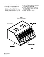
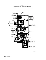
240-Volt Units (Dual switch models):
The speed of
each blower (intake and exhaust) can be controlled
independently by two (2) switches located on the left side
of the control panel, behind the WFERV front door. The
switch located on the upper part of the control panel
controls the intake blower located in the upper assembly.
The switch located on the lower part of the control panel
controls the exhaust blower located in the lower
assembly. See Figure 6
.
If desired, the intake blower can be set up for one speed
and the exhaust blower set up for another speed if needed
for the specific application.
TABLE 1
VENTILATION AIR (CFM)
)
M
F
C
(
R
I
A
N
O
I
T
A
L
I
T
N
E
V
l
e
d
o
M
d
e
e
p
S
h
g
i
H
)
k
c
a
l
B
(
d
e
e
p
S
.
d
e
M
)
e
u
l
B
(
d
e
e
p
S
w
o
L
)
d
e
R
(
V
R
E
F
W
0
5
4
0
7
3
0
8
2
ENERGY RECOVERY VENTILATOR
MAINTENANCE
GENERAL INFORMATION
The ability to clean exposed surfaces within air moving
systems is an important design consideration for the
maintenance of system performance and air quality. The
need for periodic cleaning will be a function of operating
schedule, climate, and contaminants in the indoor air
being exhausted and in the outdoor air being supplied to
the building. All components exposed to the airstream,
including energy recovery wheels, may require cleaning
in most applications.
Rotary counterflow heat exchanges (heat wheels) with
laminar airflow are “self-cleaning” with respect to dry
particles. Smaller particles pass through; larger particles
land on the surface and are blown clear as the flow
direction is reversed. For this reason, the primary need
for cleaning is to remove films of oil-based aerosols that
have condensed on energy transfer surfaces. Buildup of
material over time may eventually reduce airflow. Most
importantly, in the case of desiccant coated (enthalpy)
wheels, such films can close off micron sized pores at the
surface of the desiccant material, reducing the efficiency
with which the desiccant can absorb and desorb moisture.
FREQUENCY
In a reasonably clean indoor environment such as a
school, office building, or home, experience shows that
reductions of airflow or loss of sensible (temperature)
effectiveness may not occur for ten or more years.
However, experience also shows that measurable changes
in latent energy (water vapor) transfer can occur in
shorter periods of time in commercial, institutional and
residential applications experiencing moderate occupant
smoking or with cooking facilities. In applications
experiencing unusually high levels of occupant smoking,
such as smoking lounges, nightclubs, bars and
restaurants, washing of energy transfer surfaces, as
frequently as every six months, may be necessary to
maintain latent transfer efficiency. Similar washing
cycles may also be appropriate for industrial applications
involving the ventilation of high levels of smoke or oil-
based aerosols such as those found in welding or
machining operations, for example. In these applications,
latent efficiency losses of as much as 40% or more may
develop over a period of one to three years.
CLEANABILITY AND PERFORMANCE
In order to maintain energy recovery ventilation systems,
energy transfer surfaces must be accessible for washing to
remove oils, grease, tars and dirt that can impede
performance or generate odors. Washing of the desiccant
surfaces is required to remove contaminate buildups that
can reduce adsorption of water molecules. The continued
ability of an enthalpy wheel to transfer latent energy
depends upon the permanence of the bond between the
desiccant and the energy transfer surfaces.
Bard wheels feature silica gel desiccant permanently
bonded to the heat exchange surface without adhesives;
the desiccant will not be lost in the washing process.
Proper cleaning of the Bard energy recovery wheel will
restore latent effectiveness to near original performance.
MAINTENANCE PROCEDURES
NOTE: Local conditions can vary and affect the
required time between routine maintenance
procedures, therefore all sites (or specific units
at a site) may not have the same schedule to
maintain acceptable performance. The
following timetables are recommended and can
be altered based on local experience.
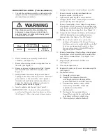
WARNING
Open circuit breaker to shut all power OFF
before doing this. Failure to do so could
result in injury or death due to electrical
shock.
Summary of Contents for WFERV-A-X
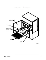
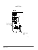
Page 10: ...Manual 2100 495A Page 10 of 21 FIGURE 5 INSTALLATION OF WFERV...
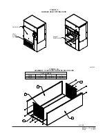
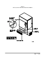
Page 11: ...Manual 2100 495A Page 11 of 21 FIGURE 6 WFERV ASSEMBLY...
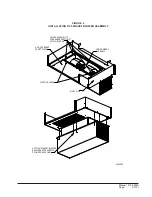
Page 13: ...Manual 2100 495A Page 13 of 21 FIGURE 8 INSTALLATION OF FRESH AIR INTAKE HOOD ASSEMBLY...
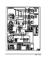
Page 18: ...Manual 2100 495A Page 18 of 21 FIGURE 10 THERMOSTAT WIRING DIAGRAM...
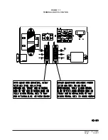
Page 19: ...Manual 2100 495A Page 19 of 21 FIGURE 11 TERMINAL BLOCK LOCATION...
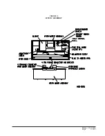
Page 20: ...Manual 2100 495A Page 20 of 21 FIGURE 12 HUB ASSEMBLY WITH BALL BEARING...
Page 21: ...Manual 2100 495A Page 21 of 21...


