Manual
2100-406A
Page
1 of 16
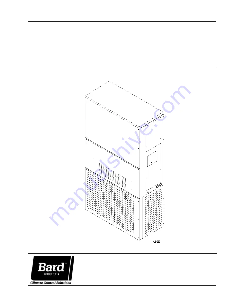
Model
: WA253
WALL MOUNTED PACKAGED
AIR CONDITIONER
INSTALLATION
INSTRUCTIONS
Manual No.:
2100-406A
Supersedes:
2100-406
File:
Volume
III
, Tab 16
Date:
07-25-06
Bard Manufacturing Company, Inc.
Bryan, Ohio 43506
Since 1914...Moving ahead just as planned.


