Manual
2100-482
Page
25 of 25
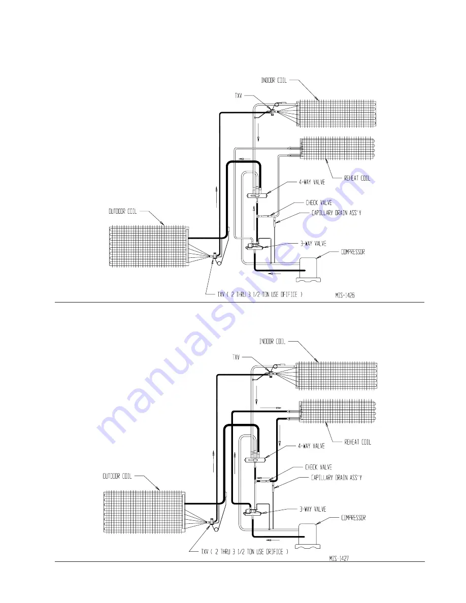
FIGURE 14
BARD HEAT PUMP COOLING MODE
CIRCUIT DIAGRAM
FIGURE 15
BARD HEAT PUMP DEHUMIDIFICATION MODE
Page 1: ...INSTALLATION INSTRUCTIONS WALL MOUNTED PACKAGE HEAT PUMPS Model SH612D Manual 2100 482 Supersedes NEW File Volume III Tab 17 Date 12 19 07 Bard Manufacturing Company Inc Bryan Ohio 43506 Since 1914 M...
Page 2: ...t Charge 23 Table 8 Rated CFM and Rated ESP 23 Table 9 Indoor Blower Performance 23 Table 10 Maximum ESP of Operation 23 Table 11 Pressure Table Cooling 24 Table 12 Pressure Table Heating 24 Getting O...
Page 3: ...ter and Summer Air Conditioning Duct Design for Residential ACCA Manual D Winter and Summer Air Conditioning and Equipment Selection FOR MORE INFORMATION CONTACT THESE PUBLISHERS ACCA Air Conditioning...
Page 4: ...0 1 B 230 208 60 3 C 460 60 3 VENTILATION OPTIONS X Barometric Fresh Air Damper Standard 1 B Blank off Plate M Motorized Fresh Air Damper 1 V Commercial Room Ventilator Motorized with Exhaust E Econom...
Page 5: ...t d i W W h t p e D D t h g i e H H y l p p u S n r u t e R E F G I J K L M N O P Q A B C B D 2 1 6 H S 2 4 4 1 2 2 8 7 4 9 8 7 9 8 7 9 2 8 7 5 1 8 7 9 2 8 7 3 4 9 1 8 5 1 4 0 3 6 1 1 1 2 4 7 3 4 3 4...
Page 6: ...r should adhere to local codes DUCT WORK Any heat pump is more critical of proper operating charge and an adequate duct system than a straight air conditioning unit All duct work supply and return mus...
Page 7: ...ordering information If using a return air filter grille filters must be of sufficient size to allow a maximum velocity of 400 fpm FILTERS A 1 inch throwaway filter is supplied with each unit The fil...
Page 8: ...2 x 12 See Figures 3 and 4 for details 3 Locate and mark lag bolt locations and bottom mounting bracket location See Figure 3 4 Mount bottom mounting bracket 5 Hook top rain flashing under back bend o...
Page 9: ...g at time of installation MIS 796 A Top flashing detail view Attach supplied rain flashing Apply caulk between flashing and wall Foam air seal Seal with bead of caulking along entire length of top Sup...
Page 10: ...is required for the first 3 feet of ducting It is important to insure that the 1 4 inch minimum spacing is maintained at all points Failure to do this could result in overheating the combustible mate...
Page 11: ...Manual 2100 482 Page 11 of 25 FIGURE 5 WALL MOUNTING INSTRUCTIONS FIGURE 6 WALL MOUNTING INSTRUCTIONS SEE UNIT DIMENSIONS FIGURE 1 FOR ACTUAL DIMENSIONS SEE FIGURE 4 MOUNTING INSTRUCTIONS...
Page 12: ...Manual 2100 482 Page 12 of 25 FIGURE 7 COMMON WALL MOUNTING INSTALLATIONS...
Page 13: ...of the disconnect opening under the disconnect access panel straight out This tab will now line up with the slot in the door When shut a padlock may be placed through the hole in the tab preventing en...
Page 14: ...Manual 2100 482 Page 14 of 25 FIGURE 8 SHXXXDX HOT GAS REHEAT DURING DEHUMIDIFICATION WITH CS2000A2 ENERGY MONITOR FULL TIME DEHUMIDIFICATION...
Page 15: ...EAT DURING DEHUMIDIFICATION WITH PROGRAMMABLE THERMOSTAT FULL TIME DEHUMIDIFICATION FIGURE 9A SHXXXDX HOT GAS REHEAT DURING DEHUMIDIFICATION WITH CS2000A2 ENERGY MONITOR AND 8406 060 THERMOSTAT WITH B...
Page 16: ...type of thermostat is variable with geographic region and sizing of the heating equipment to the structure Utilization of the Heating Application Data and the heat loss calculation of the building are...
Page 17: ...by the electronic heat pump control This is a 24 VAC output W2 terminal is second stage heat if equipped O1 terminal is the ventilation input This terminal energizes any factory installed ventilation...
Page 18: ...changed or rewired If improper rotation is corrected at this time there will be no negative impact on the durability of the compressor However reverse operation for over one hour may have a negative i...
Page 19: ...subbase for constant air circulation Refer to Figure 14 HEATING SEQUENCE On a call for heating the compressor and reversing valve of the unit are energized to provide heat pump heating If the room te...
Page 20: ...for time to elapse Use a small screwdriver or other metallic object or another 1 4 inch QC to short between the SPEEDUP terminals to accelerate the HPC timer and initiate defrost Be careful not to tou...
Page 21: ...a l e r n a f s s o r c a k c e h C l o r t n o c p m u p t a e h e c a l p e R e v i t c e f e d r o t o M r o t o m e c a l p e R g n i d n i w r o t o m d e t r o h s r o n e p o r o f k c e h C e...
Page 22: ...507 66418 64399 62449 60565 58745 56985 55284 53640 52051 50514 49028 47590 46200 44855 43554 42295 41077 25 0 26 0 27 0 28 0 29 0 30 0 31 0 32 0 33 0 34 0 35 0 36 0 37 0 38 0 39 0 40 0 41 0 42 0 43 0...
Page 23: ...ESP l e d o M d e t a R M F C d e t a R P S E d e d n e m m o c e R e g n a R w o l f r i A D 2 1 6 H S 0 5 3 1 0 2 0 0 1 1 5 7 4 1 Subtract 08 static for 2 filter TABLE 9 INDOOR BLOWER PERFORMANCE CF...
Page 24: ...i S h g i H 2 7 1 9 1 4 7 8 0 2 5 7 5 2 2 7 7 2 4 2 8 7 1 6 2 0 8 9 7 2 1 8 8 9 2 1 8 8 1 3 2 8 8 3 3 B D g e d 5 8 B W g e d 2 7 e d i S w o L e d i S h g i H 5 7 8 9 1 7 7 5 1 2 8 7 3 3 2 0 8 0 5 2...
Page 25: ...Manual 2100 482 Page 25 of 25 FIGURE 14 BARD HEAT PUMP COOLING MODE CIRCUIT DIAGRAM FIGURE 15 BARD HEAT PUMP DEHUMIDIFICATION MODE CIRCUIT DIAGRAM...