background image

R5912118 /01

UST lens for F-series

19

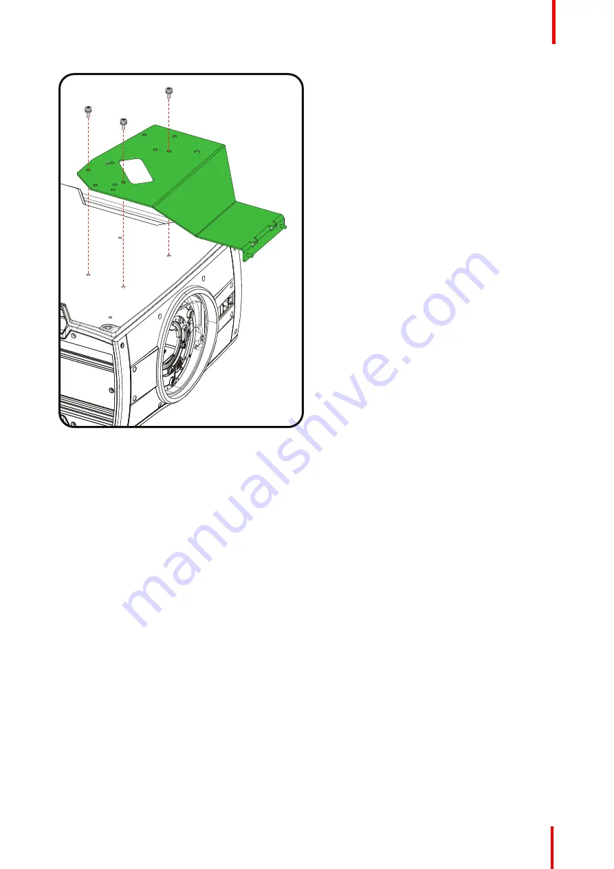
Image 2-14: Mount bottom plate

3.

Turn in the 3 M6 screws.

4.

Turn the projector back on its feet.

Slide the lens locking system to the left.

Insert the lens. Make sure the electric contact points (C) on the lens match the contact points on the lens
holder.

Mounting the lens

Summary of Contents for UST

Page 1: ...ENABLING BRIGHT OUTCOMES Installation manual UST lens for F series...

Page 2: ...Registered office Barco NV President Kennedypark 35 8500 Kortrijk Belgium www barco com en support www barco com Barco NV Beneluxpark 21 8500 Kortrijk Belgium www barco com en support www barco com...

Page 3: ...3 Overview Preparation of the lens Parts indication R5912118 01 UST lens for F series General 1...

Page 4: ...lens has to be rebuild according the its use and projector type The motor housing must be turned to the correct position before the lens is mounted in the projector The following positions for the le...

Page 5: ...ST lens for F series 5 Image 1 3 For F90 facing up and to the right Image 1 4 Do not use for projection to the right when mounted in a frame Up F80 up F80 Left Left Right 30 60 30 60 Barco 0 38 1 Imag...

Page 6: ...len key 2 mm with long shaft delivered with the kit How to prepare the lens for all F series 1 Place the lens on a table Turn out the 6 screws 1 Use an Allen key with a long shaft so that you do not d...

Page 7: ...mm 2 3 A Image 1 10 A reference marking 3 Rotate the motor housing until the chosen marker on the housing corresponds with the reference marking on the lens body steps of 30 See if the mounting holes...

Page 8: ...e lens to re engage focusing gear and motor gear 5 Turn in 6 new Allen screws with glue screws are delivered with the kit These screws can be multiple times reused The turned out old screws can be thr...

Page 9: ...3 C Side view D Bottom view Extra preparation for F80 1 Slide the lens adaptor on the lens input until it matches the motor housing 1 Make sure the contacts are on the left top of the adaptor 1 2 Imag...

Page 10: ...UST lens for F series 10 1 2 Parts indication Overview 1 4 3 2 Image 1 15 1 Bottom plate fixation screws depends on projector type 2 2th plate with 2 nuts 3 3th plate with 2 screws 4 Clamp with 2 scr...

Page 11: ...afety cable as shown in the image Overview When mounting the lens without the support Mounting the UST lens on a F90 projector Mounting the UST lens on a F70 projector Mounting the UST lens on a F40 p...

Page 12: ...e lens holder with the open ends oriented outwards 3 Make sure that both a part of the loop end and the outgoing part of the safety cable are placed in the enclosure 6 Close the U bolt and tighten it...

Page 13: ...3 Turn in both M6 screws 4 Turn the projector back on its feet Slide the lens locking system to the left Insert the lens Make sure the electric contact points C on the lens match the contact points o...

Page 14: ...ormation about shifting the image Note Shift cannot be adjusted anymore after full installation of the complete kit 7 Slide plate 2 on both threaded rods and turn a nut on each rod Do not fasten yet I...

Page 15: ...ns Fully secure both screws Image 2 7 Mount clamp bracket 10 Fully fasten the screws of the 3th plate and the nuts of the 2nd plate so that the support is fully assembled The projector is ready for us...

Page 16: ...plate 3 Turn in both M6 screws and the M4 screw 4 Turn the projector back on its feet Slide the lens locking system to the left Insert the lens Make sure the electric contact points C on the lens matc...

Page 17: ...ion about lens shift Note Shift cannot be adjusted anymore after full installation of the complete kit 7 Slide plate 2 on both threaded rods and turn a nut on each rod Do not fasten yet It must be pos...

Page 18: ...lens Fully secure both screws Image 2 13 Mount clamp bracket 10 Fully fasten the screws of the 3th plate and the nuts of the 2nd plate so that the support is fully assembled The projector is ready for...

Page 19: ...nt bottom plate 3 Turn in the 3 M6 screws 4 Turn the projector back on its feet Slide the lens locking system to the left Insert the lens Make sure the electric contact points C on the lens match the...

Page 20: ...R5912118 01 UST lens for F series 20 Image 2 15 Open locking system Image 2 16 Mounting lens Mounting the lens...

Page 21: ...ion about lens shift Note Shift cannot be adjusted anymore after full installation of the complete kit 7 Slide plate 2 on both threaded rods and turn a nut on each rod Do not fasten yet It must be pos...

Page 22: ...match with the lens Fully secure both screws Image 2 20 Mount clamp bracket 10 Fully fasten the screws of the 3th plate and the nuts of the 2nd plate so that the support is fully assembled The project...

Page 23: ...Make sure that the fixation holes match the holes in the bottom plate Image 2 21 Mount bottom plate 3 Turn in the M6 screws and the M8 bolt 4 Turn the projector back on its feet Insert the prepared l...

Page 24: ...anymore after full installation of the complete kit 6 Slide plate 2 on both threaded rods and turn a nut on each rod Do not fasten yet It must be possible to move the plate a little bit while mountin...

Page 25: ...he support Drive in both fixation screws If necessary move the 3th plate a little bit until it fully match with the lens Fully secure both screws Image 2 26 Mount clamp bracket 9 Fully fasten the scre...

Page 26: ...Barco NV Beneluxpark 21 8500 Kortrijk Belgium Registered office Barco NV President Kennedypark 35 8500 Kortrijk Belgium www barco com R5912118 01 2019 10 21...

Reviews: