background image

5. Installation procedures

2

5

0

 m

m

250 mm

20

 m

m

5

7

0

 m

m

1

4

6

2

 m

m

5

7

0

 m

m

1

9

1

0

 m

m

2

5

0

 m

m

4

0

0

 m

m

Y mm

Solaris LD 140 &120

Solaris LD 150

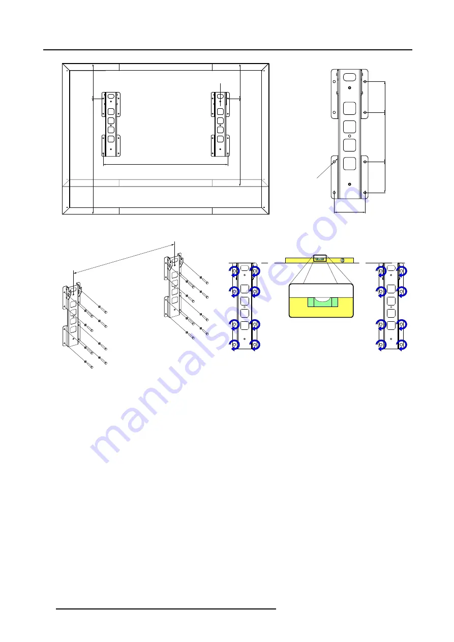
Image 5-8
Footprint of the Solaris LD wall mount adapter.

X mm

Image 5-9
Install the wall mount adapter. Lever out the top of the adapter profiles (X = Y - 250 mm).

28

R5976773 SOLARIS LD DISPLAY 02/12/2004

Summary of Contents for Solaris LD 120-8

Page 1: ...Solaris LD display Installation service manual R5976773 00 02 12 2004 ...

Page 2: ...Barco nv Media Noordlaan 5 B 8520 Kuurne Phone 32 56 36 89 70 Fax 32 56 36 83 86 E mail media barco com Visit us at the web www barco com Printed in Belgium ...

Page 3: ...f this measure proves to be impossible or unsuccessful the purchaser can demand a reduction in the purchase price or cancellation of the contract All other claims in particular those relating to compensation for direct or indirect damage and also damage attributed to the operation of software as well as to other services provided by Barco being a component of the system or independent service will...

Page 4: ......

Page 5: ...s 39 5 7 Installation of the mono phase power box 41 5 8 Installation of the Solaris D2 digitizer 42 5 9 Installation of all the Solaris LD tiles 43 5 9 1 Installation of all the Solaris LD tiles with back access to the display 44 5 9 2 Installation of all the Solaris LD tiles without back access to the display 44 5 10 Z alignment of the Solaris LD tiles 46 5 11 Installation of the filter kit 48 5...

Page 6: ...ifications 75 A 1 Specifications Solaris LD 120 8 model 75 A 2 Specifications Solaris LD 140 8 model 76 A 3 Specifications Solaris LD 140 10 model 76 A 4 Specifications Solaris LD 150 8 model 77 A 5 Specifications Solaris LD 150 10 model 78 B Order info 81 B 1 Spare part order info 81 Index 83 2 R5976773 SOLARIS LD DISPLAY 02 12 2004 ...

Page 7: ...plicate any component Barco uses specific materials and manufacturing processes in order to achieve part strength Consult Barco for assistance with custom applications Always follow Barco installation instructions Contact Barco if you should have any question regarding the safety of an application The manufacturer assumes no liability for incorrect inadequate irresponsible or unsafe assembly of sy...

Page 8: ...arts must be undertaken immediately Protect the power data cords from being walked on or pinched particularly at plugs convenience receptacles and the point where they exit from the apparatus Replace damaged power data cords immediately Only use attachments accessories specified by the manufacturer Disconnect the power to this apparatus during lightning storms or provide suitable additional lightn...

Page 9: ... destroy ing LED components do not touch either in operation or while switched off Risk of electric shock Risk of fire To protect against risk of fire by overloading of power cables MAXIMUM 7 TILES may be connected in parallel Each power source cable supplying MAXIMUM 7 TILES should be protected by a circuit breaker or fuses rated 16 A 250 VAC 15 A 250 VAC in the USA and Canada Disconnect device W...

Page 10: ... extension cord If an extension cord is used with this product make sure that the total of the ampere ratings on the products plugged into the extension cord does not exceed the extension cord ampere rating Also make sure that the total of all products plugged into the wall outlet does not exceed 15 amperes Cabinet openings Never push objects of any kind into this product through cabinet slots as ...

Page 11: ...or use The humidity level at the operating area must be between 35 and 85 To forsake this requirement will result in damage of internal parts of the Solaris LD display Ventilation A lot of energy is transferred into heat The installation should be such that the amount of air flow required for safe operation of the equipment is not compromised Proper ventilation must be provided The location of the...

Page 12: ...tz When installed in a rack the mounting should be such that no hazardous condition is achieved due to uneven mechanical loading When the mains switch located on the back of the Solaris D2 digitizer is not accessible due to rack mounting the socket outlet supplying the rack shall be installed near the equipment and be easily accessible or a readily accessible disconnect device shall be incorporate...

Page 13: ...eter resolution R9052640 Solaris LD 140 10 Full color 142 LED display with 10 millimeter resolution R9052680 Solaris LD 150 8 Full color 152 LED display with 8 millimeter resolution R9052690 Solaris LD 150 10 Full color 152 LED display with 10 millimeter resolution Available mounting kits Article No Name Content R9852600 Solaris LD 120 Wall mount kit Support brackets for a wall mount configuration...

Page 14: ...nt components of a Solaris LD display and describe their func tionality in the display system Overview Solaris LD display tiles Solaris LD supporting structure Solaris LD mounting accessories Solaris D2 digitizer Mono phase power box Solaris LD software Solaris LD filter kit optional 3 1 Solaris LD display tiles Functionality The display of the Solaris LD is built up with display tiles All tiles a...

Page 15: ...s C for diagnostic purposes A B B C Image 3 3 A Re sync unit R9851520 B Data ports C Status LED s Cabling The display tile is provided with power via a power split cable with a C13 plug Data cabling between tiles is done with a DVI DVI data cable of 0 9 meter A Image 3 4 A Power input C14 socket Image 3 5 Power split cable R9851130 Image 3 6 DVI DVI data cable of 0 9 meter R9851211 3 2 Solaris LD ...

Page 16: ...the front C Bracket mounted at the rear 3 3 Solaris LD mounting accessories Bolts nuts and washers The different types of fixation parts used to assemble the Solaris LD display are kept to a minimum Each type is packed in a bag marked with a letter going from A to J All bags are put in one box including a hardcopy of this installation manual Note that the tile fixation nuts K are not included in t...

Page 17: ...nt adapter Right floor mount adapter Mounting accessories for Solaris D2 digitizer and power box Every Solaris LD display is delivered with mounting accessories for the Solaris D2 digitizer and mono phase power box These mounting accessories allows easy attachment of the digitizer and power box to the support structure Image 3 11 Left mono phase power box adapter plate Right Solaris D2 digitizer s...

Page 18: ...D display or if desired in a separated rack The maximum length of the DVI data cable used between the Solaris D2 digitizer and the first tile of the So laris LD display may not exceed five 5 meter Neglecting this can result in non or bad performance of the Solaris LD display Image 3 14 Solaris D2 digitizer R9852780 Input slots The Solaris D2 digitizer contains two input slots Barco offers several ...

Page 19: ... the Solaris LD housing power has to be split off from the mono phase power box using a power split cable and extension lead The second basic connection is the data connection between the Solaris D2 digitizer and the first tile of the Solaris LD display This connection is realized with a DVI DVI data cable with a maximum length of five 5 meter The third basic connection is the serial communication...

Page 20: ...VI plugs R9851210 Data source cables between the Solaris LD display and external devices are not included 3 5 Mono phase power box Functionality The mono phase power box is installed at the left or right side of the display and subdivides power from the local power net into five 5 protected circuits These circuits distribute power to the Solaris LD display system Each circuit is equipped with a ca...

Page 21: ...ed input voltage of the mono phase power box Wrong input voltage can cause damage to the power box and the equipment connected with the power box 3 6 Solaris LD software Functionality The Solaris LD user software has three different levels namely Expert Operator and User level In the Expert level you can request for service information etc Within the Operator level you can program and schedule the...

Page 22: ...f Solaris LD tiles a fan unit with a filter is installed The fans are electrical connected with each other using the same kind of power split cables as used to power up the tiles Clean the Solaris LD filter on regular base A B D C Image 3 32 Optional filter kit A Power socket B Fixation point C Removable filter D Thumbscrew to open the door to the removable filter 18 R5976773 SOLARIS LD DISPLAY 02...

Page 23: ...See chapter Installation of the precision frames upon the Solaris LD support structure page 34 4 The next stage in the process is the installation of the peripherals as there are the mono phase power box and the Solaris D2 digitizer Both peripherals must be installed at the same side of the display recommended the right side when facing the front of the display See procedures Installation of the m...

Page 24: ...next sequence a Installation of the top bottom and side cladding support brackets page 49 b Installation of the top and bottom cladding page 50 c Installation of the left and right side cladding page 53 8 The second last stage in the process is the installation of the Solaris LD software on the local PC Refer to the User guide of the Solaris LD software for installation instructions 9 Finally the ...

Page 25: ...of the left and right side cladding page 53 d Installation of the rear cladding page 54 7 The second last stage in the process is the installation of the Solaris LD software on the local PC Refer to the User guide of the Solaris LD software for installation instructions 8 Finally the Solaris LD system is ready to start up After energizing the Solaris LD display and the Solaris D2 digitizer the sys...

Page 26: ...4 Set up process of a Solaris LD display 22 R5976773 SOLARIS LD DISPLAY 02 12 2004 ...

Page 27: ... 140 X 1792 mm Solaris LD 150 X 1792 mm Ensure that the feet are perfectly aligned image 5 1 image 5 2 image 5 3 2 Drill the eight mounting holes and provide them with fixation parts Warning Each fixation point between the Solaris LD foot and the floor must be able to handle a force of xxxx Newton 3 Place the Solaris LD feet into position Note that the front top side of the foot is lower than the ...

Page 28: ...5 mm Image 5 2 Footprint bottom view 780 mm 900 2 mm 3260 mm 2480 mm 2812 mm 2032 mm Solaris LD 150 Solaris LD 140 120 Image 5 3 Height and with dimensions of a floor mounted Solaris LD display 24 R5976773 SOLARIS LD DISPLAY 02 12 2004 ...

Page 29: ...st be up image 5 4 2 Attach two horizontal profiles between the two vertical profiles as illustrated Four long bolts need to be used per junction Use two M12 plain washers and a M12 spring lock washer per fixation point as illustrated Do not fasten yet just loosely attach the profiles together image 5 5 3 Fasten the four fixation points at the junction between the horizontal and vertical profiles ...

Page 30: ...age 5 5 E M12x130 hexagon head bolt B M12 plain washer C M12 spring lock washer D M12 hexagon nut 90 90 90 90 Image 5 6 The corners of the support frame must stand at a right angle before fastening 26 R5976773 SOLARIS LD DISPLAY 02 12 2004 ...

Page 31: ...e that the distance X between the centers of the two profiles depends on the chosen Solaris LD model Solaris LD 120 Y 1594 mm Solaris LD 140 Y 2042 mm Solaris LD 150 Y 2042 mm Each wall mount adapter profile contains 8 fixation holes with a diameter of 20 mm Ensure that above and below the adapter profiles is sufficient space for installing the display The hooks of the adapters must point upwards ...

Page 32: ...70 mm 1910 mm 250 mm 400 mm Y mm Solaris LD 140 120 Solaris LD 150 Image 5 8 Footprint of the Solaris LD wall mount adapter X mm Image 5 9 Install the wall mount adapter Lever out the top of the adapter profiles X Y 250 mm 28 R5976773 SOLARIS LD DISPLAY 02 12 2004 ...

Page 33: ...e two vertical profiles as illustrated Four long bolts E need to be used per junction Use two M12 plain washers B and a M12 spring lock washer C per fixation point Do not fasten yet just attach the profiles loosely together image 5 11 3 Fasten the four fixation points at each junction of the horizontal profiles with the vertical profiles of the support frame Ensure the four corners of the support ...

Page 34: ...e 5 11 Install the horizontal profiles of the support frame 90 90 90 90 Image 5 12 Fasten horizontal and vertical profiles of the support frame Image 5 13 Level out the support frame using shim plates 30 R5976773 SOLARIS LD DISPLAY 02 12 2004 ...

Page 35: ...C 16 M12 hexagon nuts D 16 M12x130 hexagon head bolts E How to install the support frame hanging on the ceiling 1 Attach the ceiling mount adapter on top of the vertical profiles as illustrated Use three M12x30 hexagon head bolts A per profile Place a M12 plain washer B and a M12 spring lock washers C on each bolt image 5 15 2 Hang up the two vertical profiles Note that the distance X between the ...

Page 36: ...ure the four corners of the support frame are standing at a right angle Use a try square to verify image 5 18 5 Level out the Solaris LD support frame using a spirit level image 5 19 A C B Image 5 15 Attach the ceiling mount adapter on top of the vertical profiles X mm Image 5 16 Hang up the two vertical profiles 32 R5976773 SOLARIS LD DISPLAY 02 12 2004 ...

Page 37: ... D Image 5 17 Attach the two horizontal profiles between the two vertical profiles 90 90 90 90 Image 5 18 Fasten the four fixation points on each junction Image 5 19 Level out the support frame R5976773 SOLARIS LD DISPLAY 02 12 2004 33 ...

Page 38: ...rame CAUTION Handle the precision frames with care Do not walk on or drop the frames Never bang with a hammer or other heavy duty tools on the precision frames Never use the precision frames to climb on to the Solaris LD display The most left and the most right precision frame on the support structure are half size precision frames Those half size precision frames do not require a height adjustmen...

Page 39: ...locations are suitable indicated with a cut out diamond to install the first precision frame 2 Loosely attach the first precision frame to the support structure by inserting one M12x30 hexagon head bolt A in the mounting hole indicated with the arrow in the detail view of image 5 22 Ensure to use a M12 plain washer B and spring lock washer C Do not fasten yet the precision frame must be able to sw...

Page 40: ...ecision frame Image 5 22 Loosely attach the first precision frame Frame must be able to swing B C A Image 5 23 Place loosely four M12x30 hexagon head bolt A with a M12 plain washer B and spring lock washer C in the mounting holes 36 R5976773 SOLARIS LD DISPLAY 02 12 2004 ...

Page 41: ... support structure Adjust the height of the precision frame by turning the bolt in or out the height adjustment bracket until the mounting holes on the frame correspond with the mounting holes on the support structure 2 Loosely attach the top and bottom tile between the two precision frames using four tile fixation nuts per tile Do not fasten yet Ensure to use the tile mounting holes on the precis...

Page 42: ...st one A M12x30 hexagon head bolts B M12 plain washer C spring lock washer K Image 5 26 Loosely attaching the first tile to the precision frames using four tile fixation nuts K 90 90 Image 5 27 Final approach of the tile must be at right angle 38 R5976773 SOLARIS LD DISPLAY 02 12 2004 ...

Page 43: ...ion frame rest upon the lower horizontal profile of the support structure Adjust the height of the precision frame by turning the bolt in or out the height adjustment bracket until the mounting holes on the frame correspond with the mounting holes on the support structure 2 Attach the top and bottom tile loosely between the last and previous precision frame using four tile fixation nuts per tile D...

Page 44: ...ides of the display image 5 32 Note The most left and the most right precision frames are half size precision frames without height adjustment Image 5 30 Adjusting the height of the last installed precision frame to fade out the seams between the tiles Image 5 31 Fasten the tile fixation nuts and the bolts of the precision frame after fading out the seams between the tiles 1 2 3 8 7 6 4 5 Image 5 ...

Page 45: ...gon flange nuts G How to install the power box 1 Open the cover door of the mono phase power box and place all the circuit breakers in the OFF position 2 Remove the front cover of the power box by releasing four screws in the corners of the cover Use a Phillips screw driver 3 Attach the power box support plate to the back of the power box as illustrated Use four M4x12 hexagon socket head cap screw...

Page 46: ...sten the two digitizer support brackets at the same side of the display where the power box is installed as illustrated Use six M6x25 hexagon socket head cap srews H and six M6 hexagon flange nuts G Note that the two support brackets are identical Install the brackets in such a way that a slot is created with the width of the digitizer image 5 35 2 Slide the Solaris D2 digitizer between the two su...

Page 47: ...talled simultaneously with the precision frames The rest of the tiles are inserted one by one column by column starting in the middle of the display It s important to follow the installation sequence of tiles showed in the image below especially when there is no back access to the display e g wall mount configuration In this case the cabling has to be done simultaneously as well Note that in case ...

Page 48: ... power split cables The power cabling must be done in a horizontal direction and one power source cable must be used per row See also chapter Power cabling diagram of the Solaris LD display page 59 for correct cabling Tip It s recommended to realize the power cabling from right to left seen from the front of the display because the shape of the power split cable allows easy cabling in this directi...

Page 49: ...Insert the next tile into the Solaris LD display Follow the tile mounting sequence showed in image 5 37 Note The final approach of the tile into the precision frame must be at right angle 5 Fasten the tile with four tile fixation nuts Use a ratchet handle with short extension bar and 10 mm hexagon socket Tip See chapter Locate and access the tile fixation nuts power socket and data ports page 65 t...

Page 50: ...n is called Z alignment A B Image 5 40 A Tile fixation nut B Tile fixation bolt with Z alignment functionality The correction exist in moving the most inner corner of the tile in the LED wall forward by adjusting the tile fixation bolt in the corre sponding corner The maximum allowed adjustment is 1 millimeter which correspond with one full turn 360 counterclockwise of the tile fixation bolt seen ...

Page 51: ... fixation bolt with released fixation nut counterclockwise until the front of the tile is aligned with the front of the neighboring tiles Use a small blade screwdriver image 5 43 Warning The maximum allowed adjustment range is 1 millimeter which correspond with a 360 turn counterclockwise of the tile fixation bolt Turn the tile fixation bolt as far as possible clockwise to know the start position ...

Page 52: ... installed on a later point of time than the installation of the display Necessary tools 5 mm hexagon Allen key 10 mm open ended spanner Necessary parts One fan assembly per column One power split cable per column Four M6 hexagon flange nuts per fan assembly G Four M6x16 hexagon socket button head cap screws per fan assembly H How to install the filter kit 1 Fasten a filter kit underneath every co...

Page 53: ...button head cap screws H How to install the cladding support brackets 1 Install at the top and at the bottom of each precision frame two top bottom cladding support brackets as illustrated The two brackets must be placed back to back and than slide into the gab in the middle of the frame Use two M6x25 hexagon socket head cap screws F and two M6 hexagon flange nuts G per pair of brackets image 5 46...

Page 54: ...rner cladding plates The middle cladding plate vary in length depending on the Solaris LD model Depending on the chosen mounting configuration the corner cladding plates have on some places a different cut out to fit around the feet are ceiling mount adapter The cladding plates are U shaped One leg of the U shaped cladding plates contains teeth which fits in the slots at the top and bottom front s...

Page 55: ...ated Keep pushing on the front of the cladding to ensure the cladding teeth stay completely inside the slots of the precision frames Use a M6x16 hexagon socket button head cap screw H in every mounting hole of the cladding plate image 5 50 4 Install the middle bottom cladding plate in the same way as the middle top cladding plate image 5 51 Note The top and bottom middle cladding is independent of...

Page 56: ...e fasten cladding plate Image 5 51 Installation of the top and bottom middle cladding Image 5 52 Select the appropriate corner cladding plate for each corner of the display Image 5 53 Top and bottom cladding completely installed 52 R5976773 SOLARIS LD DISPLAY 02 12 2004 ...

Page 57: ...ing support brackets are installed 2 Ensure all top and bottom cladding plates are installed 3 Ensure the power box and digitizer are installed at the same side of the display 4 Ensure all power and data connections are realized 5 Place the side cladding plate which contains the small cover plates against the support brackets at the side of the display where the power box and digitizer is installe...

Page 58: ...ng What has to be done The rear cladding support profiles and the rear cladding plates needs to be installed against the rear of the Solaris LD display First the cladding support profiles has to be assembled and attached to the back of the display before installing the rear cladding plates 54 R5976773 SOLARIS LD DISPLAY 02 12 2004 ...

Page 59: ...adding support profiles together with a profile connection part as illustrated Use four M6x16 hexagon socket button head cap screws per connection image 5 57 4 Attach the previous joined cladding support profiles horizontally to the back of the support frame as illustrated Use therefor 16 M12x30 hexagon head bolts A and 16 M12 plain washers B image 5 58 5 Attach the rear cladding plates one by one...

Page 60: ...lation of the foot cladding What has to be done The foot cladding support profiles and the foot cladding plates needs to be installed around the feet of the Solaris LD display First the cladding support brackets has to be attached to the feet of the display before installing the foot cladding plates 56 R5976773 SOLARIS LD DISPLAY 02 12 2004 ...

Page 61: ...s as illustrated Fasten with four M6x16 hexagon socket button head cap screws H The foot rear cladding plate is recognizable by the ventilation grid image 5 61 Note Ensure to use the rearmost mounting holes in the cladding plate for fastening The mounting holes in the rear cladding plate located more at the front must be free to install the front cladding plate of the feet 3 Install the foot front...

Page 62: ...5 Installation procedures H Image 5 62 Install foot front cladding plate 58 R5976773 SOLARIS LD DISPLAY 02 12 2004 ...

Page 63: ...cause the shape of the power split cable allows easy cabling in this direction This includes that the power box must be installed at the left side seen from the rear of the display Nevertheless if desired the power box can be installed at the other side of the display and the power cabling realized in the other direction The built in Solaris D2 digitizer D is also supplied with power from the powe...

Page 64: ... DVI linking cables E of 0 9 meter Depending on the Solaris LD model the last tile in the chain is located in the upper or lower right corner of the display seen from the rear The Solaris D2 digitizer receives its control signals from the PC running the Solaris LD software via a RS232 communication cable A One end of this 15 meter long communication cable is connected with the RS232 COM port of th...

Page 65: ... How to clean or replace the Solaris LD filters 1 Open the door of the filter assembly in the bottom cladding of the Solaris LD display by releasing the thumbscrew 2 Remove the filter 3 Clean the filter with a vacuum cleaner 4 Place the cleaned filter or a new filter back inside the filter assembly 5 Fasten the thumbscrew of the filter door 6 Repeat from step 1 until all filters of the Solaris LD ...

Page 66: ...7 Maintenance 1 2 Image 7 1 Remove dust filter 62 R5976773 SOLARIS LD DISPLAY 02 12 2004 ...

Page 67: ...rd in the XLite toolset program A video signal with black content is applied to the selected input slot of the Solaris D2 digitizer Apply another video signal to the selected input slot or select another input slot that doesn t contain black content LED wall receives no data signal from the Solaris D2 digitizer Check all data connections between local PC digitizer and LED wall Malfunction resync u...

Page 68: ... light up than replace the tile 8 3 Dark and bright LED s on the Solaris LD display Check list Situation Solution Part of the image on the Solaris LD display contains sparkling artifacts 1 Check if the data cable between the last good working tile in the data path and the next one is not damaged If so replace the data cable 2 Check if the data cable between the last good working tile in the data p...

Page 69: ...in order to achieve part strength No other parts than Barco parts are allowed Both hands must be free for servicing Solaris LD tiles in a LED wall Therefore the use of a ladder to access a tile is forbidden Only the use of a scaffold or a Z lift is allowed 9 2 Locate and access the tile fixation nuts power socket and data ports Locate and access the tile fixation nuts power socket and data ports T...

Page 70: ...rvicing Image 9 1 Access to the rear of the tile via side opening in precision frame Image 9 2 Access to the rear of the tile via bottom opening in precision frame 66 R5976773 SOLARIS LD DISPLAY 02 12 2004 ...

Page 71: ... power box 1 Remove the four M6x25 hexagon socket button head cap screws H of the cover plate covering the power box See image 9 3 2 Open the plastic cover door of the power box 9 4 Replacing a Solaris D2 input module There is no need to switch off the Solaris D2 digitizer to remove or insert an input module The input modules are hot swappable How to replace an input module of the Solaris D2 digit...

Page 72: ... cables connected with the tile you want to replace 3 Release the four tile fixation nuts Use a ratchet handle with short extension bar and 10 mm hexagon socket image 9 6 Caution Keep a firm grip on the tile while removing the tile fixation nuts to prevent the tile drops out of the display 4 Grab the tile by the handles and push it gently forward out of the display and hand the tile over to someon...

Page 73: ...ide cladding plate image 9 8 2 Disconnect the power cable and the two data cables connected with the last tile in the row wherein the tile is located you want to replace 3 Remove the disconnected tile by releasing the four tile fixation nuts with a ratchet handle with short extension bar and 10 mm hexagon socket 4 Repeat step 2 and tree until the tile you wanted to replace is removed image 9 9 5 P...

Page 74: ...ools Flat blade screw driver How to replace the resync unit 1 Release the two captive screws of the resync unit as illustrated Use a flat blade screw driver image 9 10 2 Pull out the resync unit 3 Place a new resync unit and fasten the captive screws Image 9 10 Replace the resync unit 70 R5976773 SOLARIS LD DISPLAY 02 12 2004 ...

Page 75: ... plate and two right on the plate There is no need to release the 4 bolts on the corners of the power supply image 9 12 Caution The SMPS unit is electrical connected via board to board connectors with the tile controller unit underneath the SMPS unit 4 Place a new SMPS unit inside the tile and fasten with eight bolts Torx TX20 5 Reinstall the cover plate of the tile Tip Clean the inside of the til...

Page 76: ...manual for more detailed instructions 2 Disconnect the wire unit of the fan from the power supply image 9 13 3 Separate the power supply from the steel plate by releasing the four bolts in the corners of the power supply Use a Torx TX20 screw driver image 9 14 4 Attach the power supply upon a new steel plate with new fan Fasten with four screws 5 Connect the wire unit of the fan with the power sup...

Page 77: ...e tile with pressed air before closing up the tile Always disconnect the wire unit of the fan before starting to blow out the dust Otherwise the fan may act as a generator and induce high current which can cause damage to the power supply unit Reconnect the wire unit after cleaning R5976773 SOLARIS LD DISPLAY 02 12 2004 73 ...

Page 78: ...ding plate s Note The side cladding plate has to be removed first before removing the cladding plate in the bottom corner 2 Unplug the power split cable from the dust filter unit 3 Remove the dust filter unit by releasing the four M6x16 hexagon socket button head cap screws and flange nuts Use a 5 mm hexagon Allen key and a 10 mm open ended spanner 4 Install a new dust filter unit Fasten with four...

Page 79: ...0 brightness Vert viewing angle 145 min 50 brightness Lifetime 100 000h typ use 45 000h full white half brightness Processing 12 bit color Colors 68 7 billion Refresh rate 400 Hz Power consumption 1 920W Avg 7 680W Max Temperature range operating 0 to 40 C 32 to 140 F storage 20 to 60 C 4 to 140 F Cabinet dimensions width 2924mm 115 height 2028mm 80 depth 330mm 13 Weight 550kg 1212lbs excl opt mou...

Page 80: ...h full white half brightness Processing 12 bit color Colors 68 7 billion Refresh rate 400 Hz Power consumption 2 240W Avg 8 960W Max Temperature range operating 0 to 40 C 32 to 140 F storage 20 to 60 C 4 to 140 F Cabinet dimensions width 3372mm 133 height 2028mm 80 depth 330mm 13 Weight 620kg 1367lbs excl opt mounting Image processing device D2 A 3 Specifications Solaris LD 140 10 model Specificat...

Page 81: ...140 F Cabinet dimensions width 3372mm 133 height 2028mm 80 depth 330mm 13 Weight 620kg 1367lbs excl opt mounting Image processing device D2 A 4 Specifications Solaris LD 150 8 model Specifications Display size diagonal 152 W x H 3136mm x 2240 mm 124 x 88 surface 7 m 76 ft LED type 3 in 1 SMD Pixel pitch 8 mm Resolution 392 x 280 Brightness 1200 NIT 1000 NIT display calibrated at 6500 K Hor viewing...

Page 82: ...ions Display size diagonal 152 W x H 3136mm x 2240 mm 124 x 88 surface 7 m 76 ft LED type 3 in 1 SMD Pixel pitch 10 mm Resolution 308 x 220 Brightness 1200 NIT 1000 NIT display calibrated at 6500 K Hor viewing angle 145 min 50 brightness Vert viewing angle 145 min 50 brightness Lifetime 100 000h typ use 45 000h full white half brightness Processing 12 bit color Colors 68 7 billion Refresh rate 400...

Page 83: ...A Specifications Cabinet dimensions width 3372mm 133 height 2476mm 97 depth 330mm 13 Weight 760kg 1675lbs excl opt mounting Image processing device D2 R5976773 SOLARIS LD DISPLAY 02 12 2004 79 ...

Page 84: ...A Specifications 80 R5976773 SOLARIS LD DISPLAY 02 12 2004 ...

Page 85: ...ule for digitizer R9850920 CVBS S VID input module for digitizer R9850940 YUV RG s B input module for digitizer R9851710 RGB analog input module for digitizer R9850930 Dummy input module for digitizer R9827560 15 meter long data cable with SUBD plugs for RS232 connection between local PC and digitizer R9851210 5 meter long data cable with DVI plugs for data connection between digitizer and first t...

Page 86: ...B Order info 82 R5976773 SOLARIS LD DISPLAY 02 12 2004 ...

Page 87: ...8 Foot cladding 56 Height adjustment bracket 34 Power box 41 Precision frames 34 35 37 39 Procedures 23 Rear cladding 54 Requirements 7 Side cladding 49 53 Solaris D2 42 Solaris LD feet 23 Support frame 25 29 31 TIles 43 44 Top cladding 50 Wall mount adapter 27 29 L LED s 64 Sparkling 64 Locate 65 Tile data ports 65 Tile fixation nuts 65 Tile power socket 65 M Maintenance 61 N No image 63 On displ...

Page 88: ...allation 23 Specifications 75 78 Solaris LD 120 8 75 Solaris LD 140 10 76 Solaris LD 140 8 76 Solaris LD 150 10 78 Solaris LD 150 8 77 Support frame 25 29 31 Ceiling mount adapter 31 Floor mount adapter 25 Installation 25 29 31 Wall mount adapter 29 Support structure 11 T Tiles 10 43 44 Installation 43 44 Top cladding 50 Installation 50 Troubleshooting 63 W Wall mount adapter 12 27 29 Installation...

Reviews: