12. Warping
12.4.8 Add a hard edge
What can be done ?
A horizontal or vertical line can be set on the grid as a hard edge. The nodes on this line are
fi
xed and
cannot be in
fl
uenced by a move of other nodes. This hard edge insertion can be done before or after node
manipulations.
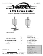
Practical example: when projecting to a corner, one part of the image is displayed on one side and the
other part on the other side of the corner, than a hard edge can be set just in the corner to
fi
xate these
nodes so that the image breaks exactly in the corner.
1
Image 12-32
Hard edge in corner
Limitations
Some limitations must be taken in account will adding a hard edge.
1. Hard edges should stay 32 pixels from the border of the image.
2. Vertical hard edge are a multiple of 4 pixels. That means that a vertical hard edge can be placed on
32 or 36 or 40, etc. pixels from the border.
3. Horizontal hard edge are a multiple of 8 pixels. That means that a horizontal hard edge can be placed
on 32 or 40 or 48, etc pixels from the border.
Only one horizontal and one vertical hard edge can be added.
How to add
1. Select the radio button in front of Manipulate hard edges (1). (image 12-33)
The
Floating
menu changes.
2. Click on Add vertical (A) and or Add horizontal hard edge (B) icon on the Floating menu.
A line is added on the grid.
Red line : selected hard edge
Green line : non selected hard edge
128
R59770513 RLM W-SERIES 28/07/2010
Summary of Contents for RLM W Series
Page 1: ...RLM W series Reference manual R59770513 01 28 07 2010 ...
Page 4: ......
Page 8: ...Table of contents 4 R59770513 RLM W SERIES 28 07 2010 ...
Page 36: ...3 Menus Image 3 15 Clear short cut on snapshot 32 R59770513 RLM W SERIES 28 07 2010 ...
Page 46: ...4 Preferences Image 4 13 Selecting a workspace 42 R59770513 RLM W SERIES 28 07 2010 ...
Page 67: ...5 Configurator Image 5 21 Multi selection of projectors R59770513 RLM W SERIES 28 07 2010 63 ...
Page 68: ...5 Configurator 64 R59770513 RLM W SERIES 28 07 2010 ...
Page 78: ...6 General projector settings 74 R59770513 RLM W SERIES 28 07 2010 ...
Page 97: ...8 Adjustments Image 8 15 Input balance R59770513 RLM W SERIES 28 07 2010 93 ...
Page 98: ...8 Adjustments 94 R59770513 RLM W SERIES 28 07 2010 ...
Page 104: ...10 Installation 100 R59770513 RLM W SERIES 28 07 2010 ...
Page 106: ...11 Communication 102 R59770513 RLM W SERIES 28 07 2010 ...
Page 111: ...12 Warping Image 12 5 Normal warping rotation R59770513 RLM W SERIES 28 07 2010 107 ...
Page 150: ...Index 146 R59770513 RLM W SERIES 28 07 2010 ...