


12. Warping
The position of all the other nodes in the active area is recalculated with regard to the new position of
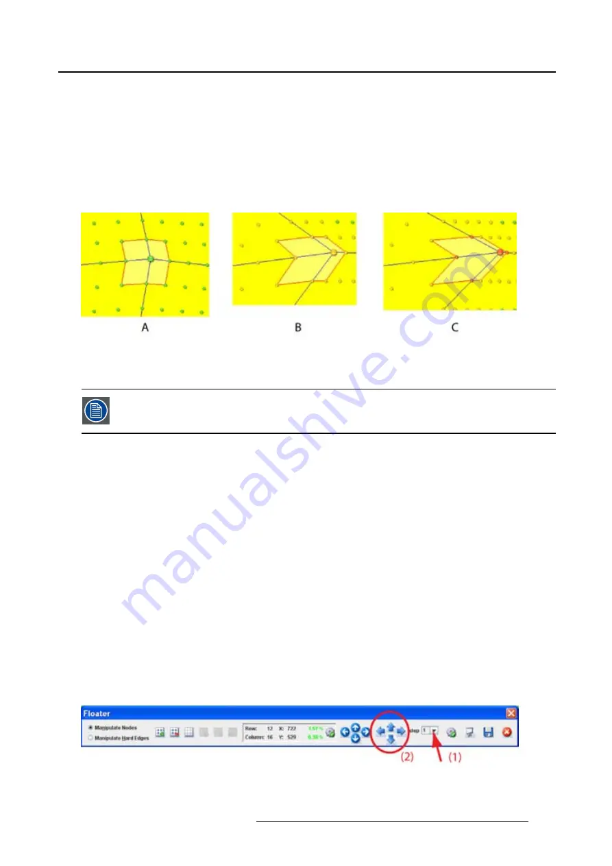
the active node. (image 12-30)
As long as the dots remain green, the warping board can execute this new position. The coordinates
and the status icon of the selected active node are also green;
When the dots become orange, a possible problem can occur on the warping board. The coordinates
values change also to orange and the status icon goes to the error state.
When the dots become red, the warping board is possibly not able to execute these settings. The
coordinates values change also to red and the status icon goes to the warning state.
Image 12-30
A
Normal status indication
B
Error status indication
C Warning status indication
To solve this problem, go to a higher resolution (more active nodes) and change
fi
rst
some adjacent nodes before returning to the original node.
12.4.7 Making an adjustment via the Floater menu or keyboard
About the arrow keys
Click in on the arrow keys of the
Floater
menu is the same as pressing
Ctrl
+
arrow key
on the keyboard.
How to make the adjustment
1. Select the active node to move.
2. Before starting, set
fi
rst the adjustment step. Click on the drop down box next to
Step
in the
Floating
menu and select the number of pixels one step represents. (image 12-31)
3. Click on the arrow keys to move the node in the desired direction. Each click represents a jump of x
pixels where x is the number set in Step.
As long as the dots remain green, the warping board can execute this new position. The coordinates
and the status icon of the selected active node are also green;
When the dots become orange, a possible problem can occur on the warping board. The coordinates
values change also to orange and the status icon goes to the error state.
When the dots become red, the warping board is not able to execute these settings. The coordinates
values change also to red and the status icon goes to the warning state.
Image 12-31
R59770513 RLM W-SERIES 28/07/2010
127
Summary of Contents for RLM W Series
Page 1: ...RLM W series Reference manual R59770513 01 28 07 2010 ...
Page 4: ......
Page 8: ...Table of contents 4 R59770513 RLM W SERIES 28 07 2010 ...
Page 36: ...3 Menus Image 3 15 Clear short cut on snapshot 32 R59770513 RLM W SERIES 28 07 2010 ...
Page 46: ...4 Preferences Image 4 13 Selecting a workspace 42 R59770513 RLM W SERIES 28 07 2010 ...
Page 67: ...5 Configurator Image 5 21 Multi selection of projectors R59770513 RLM W SERIES 28 07 2010 63 ...
Page 68: ...5 Configurator 64 R59770513 RLM W SERIES 28 07 2010 ...
Page 78: ...6 General projector settings 74 R59770513 RLM W SERIES 28 07 2010 ...
Page 97: ...8 Adjustments Image 8 15 Input balance R59770513 RLM W SERIES 28 07 2010 93 ...
Page 98: ...8 Adjustments 94 R59770513 RLM W SERIES 28 07 2010 ...
Page 104: ...10 Installation 100 R59770513 RLM W SERIES 28 07 2010 ...
Page 106: ...11 Communication 102 R59770513 RLM W SERIES 28 07 2010 ...
Page 111: ...12 Warping Image 12 5 Normal warping rotation R59770513 RLM W SERIES 28 07 2010 107 ...
Page 150: ...Index 146 R59770513 RLM W SERIES 28 07 2010 ...


