3. Installation Guidelines
PD
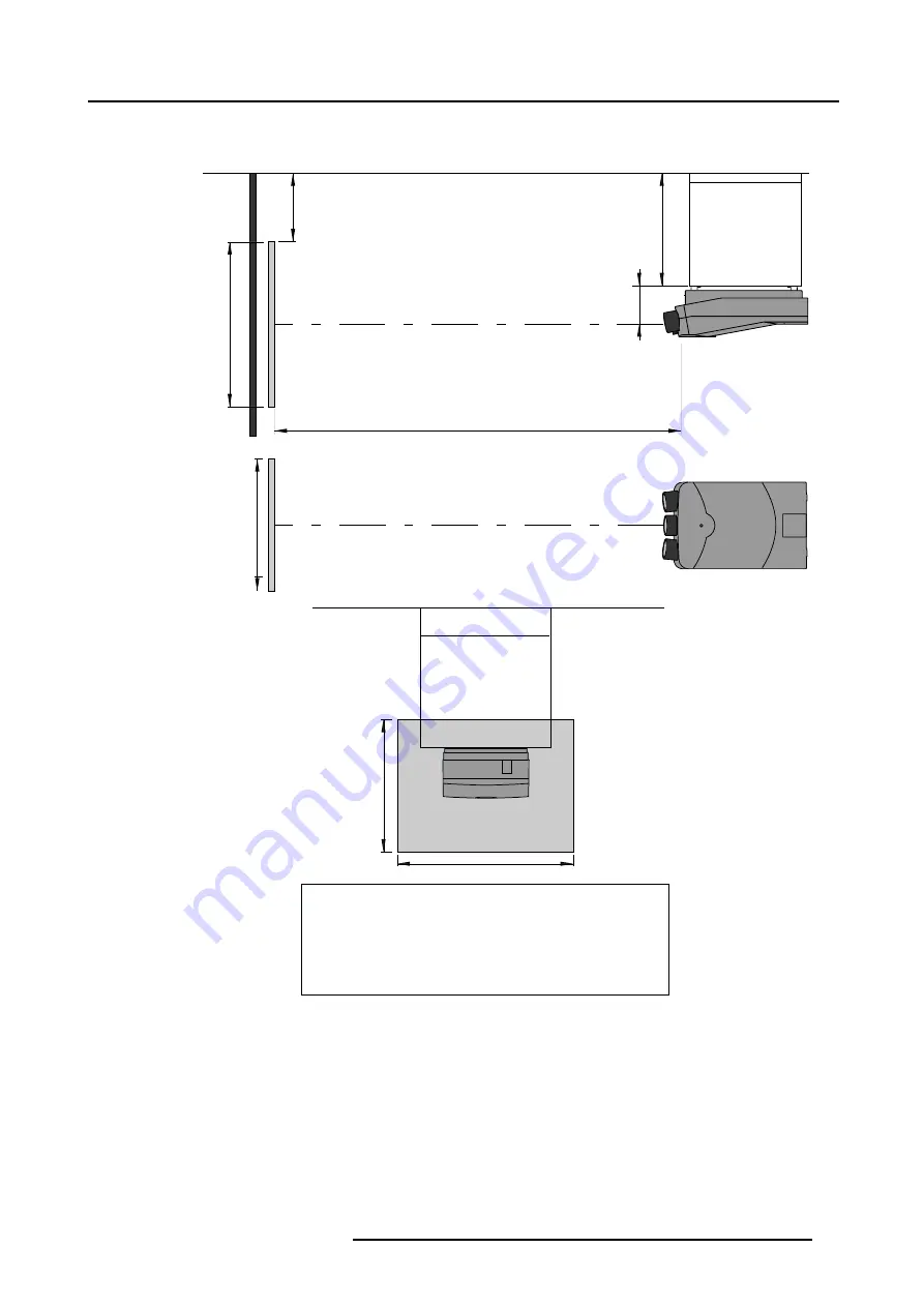
Optical axis projection lens
Ceiling
Side view
Top view
Back view
Screen
Screen
B
SH
SW
SH
SW
Ceiling
Ceiling/Top side facing floor
Projector
CD=SH/2+B-A
A
Definitions on the abbreviation on the drawings:
A = Correction value
B = Distance between ceiling and bottom of the screen
CD = Total distance between projector and ceiling
SW = Screen Width
SH = Screen Height (Image height)
PD = Projector Distance, distance between screen and projector
Image 3-5
Front/Ceiling Positioning
R5976257 BARCO REALITY 909 15/03/2003
15
Summary of Contents for Reality 909
Page 1: ...Barco Reality 909 Installation Manual R9040014 R5976257 01 15 03 2003 ...
Page 4: ......
Page 6: ...Table of contents 2 R5976257 BARCO REALITY 909 15 03 2003 ...
Page 10: ...1 Safety Instructions 6 R5976257 BARCO REALITY 909 15 03 2003 ...
Page 14: ...2 Packaging and Dimensions 10 R5976257 BARCO REALITY 909 15 03 2003 ...
Page 26: ...4 Installation Setup 22 R5976257 BARCO REALITY 909 15 03 2003 ...
Page 30: ...5 AC Power 26 R5976257 BARCO REALITY 909 15 03 2003 ...
Page 50: ...7 Installation Adjustment Mode 46 R5976257 BARCO REALITY 909 15 03 2003 ...
Page 56: ...A Gamma Corrections 52 R5976257 BARCO REALITY 909 15 03 2003 ...
Page 60: ...B Material Safety Data Sheet 56 R5976257 BARCO REALITY 909 15 03 2003 ...


