7. Advanced
Note that the dialog box is transparent so as to allow the preview of the adjustment over the whole screen
during the adjustment (the image to be adjusted is not hidden by the dialog box)
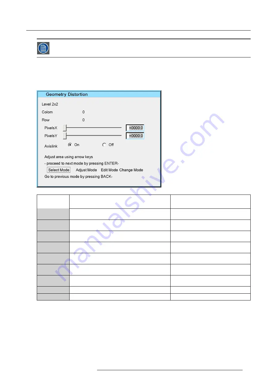
Description of the Edit dialog box
An intuitive user interface is used to perform all the geometry corrections. This gives the user real-time access to the distortion
characteristics. Each individual point can be selected and shifted to the desired location in real time.
Depending on the geometry mode, the dialog box may slightly differ, the dialog box below is for a
2x2
mode adjustment.
Image 7-40
Field
/adjustment
Description
Notes
Level 2x2
gives the selected geometry adjustment. In this case, a
2x2 adjustment
Colom
column corresponding to the selected point
in a 2x2 adjustment column will be between 0
and 32 (steps of 32)
Row
row corresponding to the selected point
in a 2x2 adjustment row will be between 0 and
32 (steps of 32)
PixelX
this slider box adjusts the new position of the point along
the x axis
in a 2x2 adjustment PixelX will be between 0
and 32(steps of 0.1 pixels)
PixelY
this slider box adjusts the new position of the point along
the y axis
in a 2x2 adjustment PixelY will be between 0
and 32 (steps of 0.1 pixels)
edit box PixelX
this edit box allows to edit the position of the point along
the x axis
edit box PixelY
this edit box allows to edit the position of the point along
the y axis
Axislink
see ’Axislink’
Modes
see ’Geometry Edit Modes’
Table 7-2
dialog box legend
7.5.6.3
Geometry Edit Modes
The geometry Edit Modes
•
Select mode : allows to select the desired area on the screen using the arrows. From 0 to 32 along the x and y axis.
•
Adjust mode : allows to perform the correction (in real time) using the arrows. The adjustment is done in small steps of 0.1
pixels.
•
Edit mode : allows to select the desired control (edit box, ...) in the dialog box.
•
Change mode : allows to change the values in the controls (edit box, radio buttons, ...) of the dialog box.
R59770198 BARCO SIM 7D 13/02/2013
75
Summary of Contents for R92112071
Page 1: ...Barco SIM 7D User Guide R92112071 R92112072 R92112073 R59770198 10 13 02 2013 ...
Page 8: ...Table of contents 4 R59770198 BARCO SIM 7D 13 02 2013 ...
Page 10: ...1 Introduction 6 R59770198 BARCO SIM 7D 13 02 2013 ...
Page 14: ...2 Packaging 10 R59770198 BARCO SIM 7D 13 02 2013 ...
Page 39: ...4 Installation Image 4 40 Location of the IR receivers R59770198 BARCO SIM 7D 13 02 2013 35 ...
Page 40: ...4 Installation 36 R59770198 BARCO SIM 7D 13 02 2013 ...
Page 54: ...5 Setup 50 R59770198 BARCO SIM 7D 13 02 2013 ...
Page 80: ...7 Advanced Image 7 41 Image 7 42 Image 7 43 76 R59770198 BARCO SIM 7D 13 02 2013 ...
Page 108: ...7 Advanced Image 7 95 Image 7 96 Image 7 97 Image 7 98 104 R59770198 BARCO SIM 7D 13 02 2013 ...
Page 154: ...7 Advanced 150 R59770198 BARCO SIM 7D 13 02 2013 ...
Page 174: ...B GLD alignment 170 R59770198 BARCO SIM 7D 13 02 2013 ...
Page 176: ...Glossary 172 R59770198 BARCO SIM 7D 13 02 2013 ...
Page 182: ...List of tables 178 R59770198 BARCO SIM 7D 13 02 2013 ...


