6. Getting started
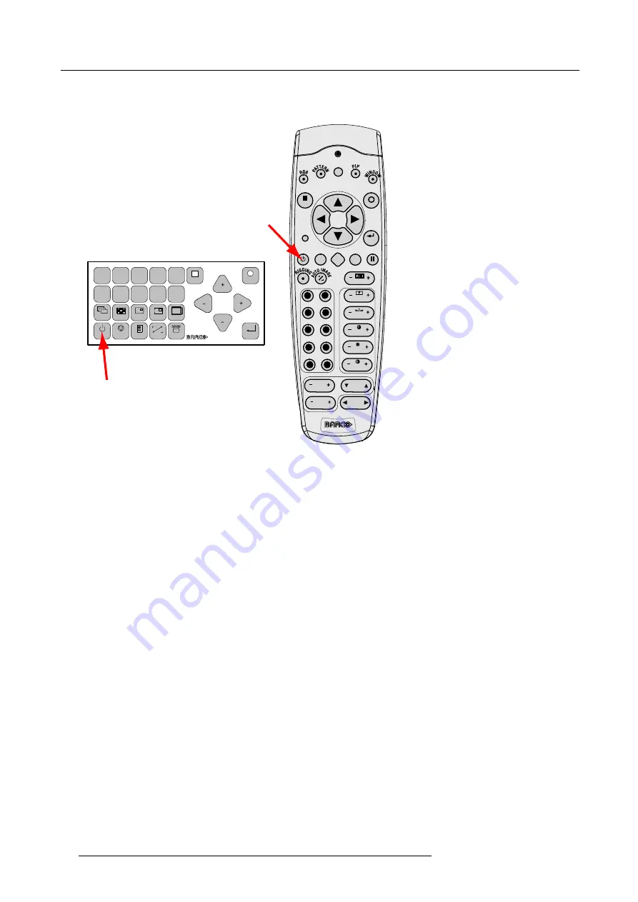
Starting image projection via the standby key.
1. Press
Stand by
key once on the local keypad or on the remote control.
MENU
EXIT
ENTER
PAUSE
TEXT
PHASE
TINT
COLOR
BRIGHTN
CONTR
9
0
7
8
5
6
3
4
1
2
LENS
LENS
ZOOM
LENS
SHIFT
LENS
FOCUS
L
SHARPN
LENS
SHIFT
1
2
3
4
5
6
7
8
9
0
MENU
EXIT
ENTER
RGB
STBY
PAUSE
TEXT
PATTERN
WINDOW
PIP
LENS
RIGGING
AUTO
A
B
Image 6-3
Stand by indication
A
Stand by indication on local keypad
B
Stand by indication on remote control
The projector status LED lights up.
The projector starts up on the last saved source.
Some lamp and runtime warnings can be displayed when an image is displayed after a start up.
6.3.2
Errors, warnings and messages during start up
Temperature error DMD
When the temperature of the DMD is too low or too high, the projector produces an error message.
When the DMD temperature is too low:
•
Lower than 0°C, warning is displayed on the LCD panel and yellow warning LED is on. Both remains until the temperature is
above 10°C.
•
Between 0°C and 10°C, projector starts up normally with a warning on the LCD panel and the yellow warning LED lights up,
but only for 10 minutes. When the temperature is then not above 10°C the projector goes in standby.
When the DMD temperature is too high:
•
When temperature is between 60°C and 65°C, the lamp mode will be reduced from 4 lamps to 2 lamps or 1 lamp.
•
When temperature is higher than 65°C, the projector switches to standby.
For a list of possible error codes, see "Error codes", page 207.
6.3.3
Switching to standby
How to switch to standby?
1. Press
Standby
to switch the projector to standby.
A cool-down counter (after cooling) starts counting down for 5 minutes (only visible on the local LCD panel). During this period
the fans are still running.
A restart is possible during this period.
48
R59770021 CLM R10+ 15/03/2010
Summary of Contents for R9050100
Page 1: ...CLM R10 Users manual R9050100 R90501001 R59770021 10 15 03 2010...
Page 14: ...1 Safety 10 R59770021 CLM R10 15 03 2010...
Page 22: ...2 General 18 R59770021 CLM R10 15 03 2010...
Page 35: ...3 Physical installation Skew Image 3 28 Skew adjustment R59770021 CLM R10 15 03 2010 31...
Page 36: ...3 Physical installation 32 R59770021 CLM R10 15 03 2010...
Page 48: ...5 Connections 44 R59770021 CLM R10 15 03 2010...
Page 64: ...7 Start up of the Adjustment mode 60 R59770021 CLM R10 15 03 2010...
Page 74: ...8 Input menu 70 R59770021 CLM R10 15 03 2010...
Page 116: ...10 Layout menu 112 R59770021 CLM R10 15 03 2010...
Page 158: ...13 Projector control 154 R59770021 CLM R10 15 03 2010...
Page 172: ...14 Service menu 168 R59770021 CLM R10 15 03 2010...
Page 186: ...16 Servicing 182 R59770021 CLM R10 15 03 2010...
Page 196: ...17 Projector covers removal and installation 192 R59770021 CLM R10 15 03 2010...
Page 204: ...C DMX Chart 200 R59770021 CLM R10 15 03 2010...
Page 210: ...D Specifications 206 R59770021 CLM R10 15 03 2010...
Page 216: ...E Troubleshooting 212 R59770021 CLM R10 15 03 2010...
Page 222: ...F Mounting optional Carry handle 218 R59770021 CLM R10 15 03 2010...
Page 224: ...G Order info 220 R59770021 CLM R10 15 03 2010...


