background image

INSTALLATION ADJUSTMENTS

INSTALLATION 

ADJUSTMENTS

INSTALLATION ADJUSTMENTS

INSTALLATION 

ADJUSTMENTS

7-7

7-7

5975069A BARCOVISION 708 200498

5975069A BARCOVISION 708 200498

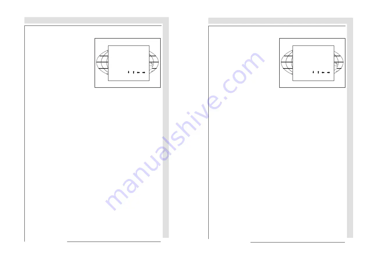
b) adjusting the projector with the local keypad.

When the 'compose password' menu is

displayed, select with the control disc

the  first  digit  of  your  password  and

press 

ENTER

.  Continue by selecting

the  second  digit  with  the  control  disc

and press 

ENTER

.  Handle in the same

way for the third and fourth digit.

When  your  password  is  correct,  you

get access to the 'Adjustment mode'.

When the entered password is wrong,

the message 

'Wrong password'

 will be

displayed.

COMPOSE

PASSWORD

????

7  8  9

4  5  6

1  2  3

0

Select with      ,      ,     or

then  <ENTER>

<EXIT>  to  return.

Summary of Contents for R9002327

Page 1: ...ROJECTIONSYSTEMS BARCOPROJECTIONSYSTEMS INSTALLATIONMANUAL INSTALLATIONMANUAL Date 200498 Date 200498 Rev 02 Rev 02 Art No R5975069A Art No R5975069A R9002328 R9002327 VISION 708 R9002328 R9002327 VISION 708 ...

Page 2: ...eir respective owners BARCO nv Projection Systems Noordlaan 5 8520 Kuurne Belgium Printed in Belgium Due to constant research the information in this manual is subject to change without notice Produced by BARCO NV April 1998 All rights reserved Trademarks are the rights of their respective owners BARCO nv Projection Systems Noordlaan 5 8520 Kuurne Belgium Printed in Belgium ...

Page 3: ...er centering 7 12 CRT projection angle adjustment 7 14 Alignment of the projector 7 18 Appendix A Ceiling mount kit for 700 projectors A 1 Appendix B G2 adjustment B 1 WARNINGS 1 1 SAFETYINSTRUCTIONS 1 1 On safety 1 4 On installation 1 5 On servicing 1 6 On cleaning 1 6 On re packing 1 7 Onillumination 1 7 UNPACKING DIMENSIONS 2 1 Unpacking 2 2 Projector dimensions 2 3 INSTALLATIONGUIDELINES 3 1 E...

Page 4: ... 1 1 5975069ABARCOVISION708200498 5975069ABARCOVISION708200498 WARNINGS SAFETY INSTRUCTIONS on safety on installation on servicing on cleaning on re packing on illumination WARNINGS SAFETY INSTRUCTIONS on safety on installation on servicing on cleaning on re packing on illumination ...

Page 5: ...afety critical components materials and isolation in order to protect the user or operator against risk of electric shock and energy hazard and having access to live parts Safety standards also impose limits to the internal and external temperature rises radiation levels mechanical stability and strength enclosure construction and protection against the risk of fire Simulated single fault conditio...

Page 6: ...ation of this equipment in a residential area is likely to cause harmful interference in which case the user will be required to correct the interference at his own expense The lightning flash with an arrowhead within a triangle is intended to tell the user that parts inside this product may cause a risk of electrical shock to persons The exclamation point within a triangle is intended to tell the...

Page 7: ... plug will only fit into a grounding type power outlet This is a safety feature If you are unable to insert the plug into the outlet contact your electrician to replace your obsolete outlet Do not defeat the purpose of the grounding type plug WARNING FOR THE CUSTOMERS THIS APPARATUS MUST BE GROUNDED EARTHED via the supplied 3 conductor AC power cable If the supplied power cable is not the correct ...

Page 8: ...r servicing to qualified service personnel under the following conditions a When the power cord or plug is damaged or frayed b If liquid has been spilled into the projector 3 Do not allow anything to rest on the power cord Do not locate this product where persons will walk on the cord To disconnect the cord pull it out by the plug Never pull the cord itself 4 If an extension cord is used with this...

Page 9: ...ion In order to obtain the best quality for the projected image it is essential that the ambient light which is allowed to fall on the screen be kept to an absolute minimum c If the product has been exposed to rain or water d If the product does not operate normally when the operating instructions are followed Note Adjust only those controls that are covered by the operating instructions since imp...

Page 10: ...led are non reflecting dark surfaces Brighter surfaces will tend to reflect and diffuse the ambient light and hence reduce the contrast of the projected image on the screen When installing the projector and screen care must be taken to avoid exposure to ambient light directly on the screen Avoid adverse illumination on the screen from direct sunlight or fluorescent lighting fixtures The use of con...

Page 11: ... 1 2 1 UNPACKING AND DIMENSIONS UNPACKINGANDDIMENSIONS UNPACKINGANDDIMENSIONS UNPACKING AND DIMENSIONS 5975069ABARCOVISION708200498 5975069ABARCOVISION708200498 UNPACKING DIMENSIONS UNPACKING DIMENSIONS ...

Page 12: ...packed at the factory Unpacking To open de banding pull on the clip as shown in the first drawing Take the projector out of its shipping carton and place it on a table Save the original shipping carton and packing material they will come in handy if you ever have to ship your projector For maximum protection re pack your projector as it was originally packed at the factory Contents of the shipped ...

Page 13: ...2 3 2 3 UNPACKING AND DIMENSIONS UNPACKINGANDDIMENSIONS UNPACKINGANDDIMENSIONS UNPACKING AND DIMENSIONS 5975069ABARCOVISION708200498 5975069ABARCOVISION708200498 Projectordimensions Projectordimensions ...

Page 14: ...STALLATION GUIDELINES Environment What about ambient light Which screen type What image size How big should the image be Where to install the projector How to install the projector INSTALLATION GUIDELINES Environment What about ambient light Which screen type What image size How big should the image be Where to install the projector How to install the projector ...

Page 15: ... the point where there is just sufficient light to read or write comfortably Spot lighting is desirable for illuminating small areas so that interference with the screen is minimal Installation guidelines Careful consideration of things such as image size ambient light level projector placement and type of screen to use are critical to the optimum use of the projection system Environment Do not in...

Page 16: ...cted images and those for rear projection applications Screens are rated by how much light they reflect or transmit in the case of rear projection systems given a determined amount of light projected toward them The GAIN of a screen is the term used Front and rear screens are both rated in terms of gain The gain of screens range from a white matte screen with a gain of 1 x1 to a brushed aluminized...

Page 17: ...ing and diagrams on next pages B Distance between ceiling and top of the screen A Correction Value extra value to be added to B to obtain the correct installation position In some cases the A value can be negative CD Total distance between projector and ceiling CD A B When the result is negative enlarge the distance between ceiling and top of the screen mount screen lower until CD becomes zero or ...

Page 18: ...ONGUIDELINES INSTALLATION GUIDELINES 3 5 INSTALLATION GUIDELINES 3 5 5975069ABARCOVISION708200498 5975069ABARCOVISION708200498 3 SURMHFWRU FHLOLQJ VFUHHQ ZLGWK 6 URQW YLHZ 7RS YLHZ 3 SURMHFWRU FHLOLQJ VFUHHQ ZLGWK 6 URQW YLHZ 7RS YLHZ ...

Page 19: ...t adaptable projection table provides a stable stand for your projector and makes it possible to adapt the projector perfectly to the local requirements BARCO order number R9827740 How to install the projector Ceiling mount or table mount To install the projector apply always the BARCO kits which are specially designed for this function BARCO ceiling support Always use the BARCO ceiling support to...

Page 20: ...LATION SET UP 4 1 INSTALLATION SET UP 4 1 INSTALLATION SET UP 5975069ABARCOVISION708200498 5975069ABARCOVISION708200498 INSTALLATION SET UP Access to controls Scanadaptation INSTALLATION SET UP Access to controls Scanadaptation ...

Page 21: ... as follow Turn both lock screws with a screwdriver or a coin counter clockwise Lift up and pivot the top cover Accesstocontrols Opening procedure During the projector set up and installation it is necessary to open the top cover To gain access handle as follow Turn both lock screws with a screwdriver or a coin counter clockwise Lift up and pivot the top cover Support the top cover with the hand n...

Page 22: ...et hinges Pivot the top cover 30 and pull it backwards until it fits in the hinges Close the cover and secure the lock screws by turning clockwise with a screwdriver or coin During some installations it will become handy to remove the top cover totally Therefore pivot the top cover 60 push the top cover to the front side of the projector until it jumps out of its hinges Turn the top cover till 90 ...

Page 23: ...emove it see Getting access to controls To open the chassis loosen both indicated retaining screws Scan adaptation The scanning can be switched by turning the Horizontal and Vertical scan connectors and the convergence connectors To change the scanning it is necessary to open the projector top cover and to rotate the chassis For opening the projector s top cover see Getting access to controls WARN...

Page 24: ...069ABARCOVISION708200498 RUL RQWDO VFDQ FRQQHFWRUV 9HUWLFDO VFDQ FRQQHFWRUV RQYHUJHQFH FRQQHFWRUV COMM PORT 800 peripherals REMOTE R G S B S VIDEO S VIDEO RS232 OUT RS232 IN RUL RQWDO VFDQ FRQQHFWRUV 9HUWLFDO VFDQ FRQQHFWRUV RQYHUJHQFH FRQQHFWRUV COMM PORT 800 peripherals REMOTE R G S B S VIDEO S VIDEO RS232 OUT RS232 IN ...

Page 25: ...onnectors must be plugged in with the contacts facing the tubes A Horizontal scan inversion Three connectors are used one for each horizontal deflection coil When changing the horizontal scan insure that all three connectors are set in the same position See position of the connectors for the corresponding projector configuration B Vertical scan inversion Three connectors are used one for each vert...

Page 26: ...ENT COMMON SETTINGS I C DIAGNOSTICS After scan inversion close the chassis and close the top cover Reconnect the power cord to the wall outlet Note Switching over from floor to ceiling or vice versa requires a complete readjustment of picture geometry and convergence Check of the correct connector position Note this check procedure can only be done after power mains connection So first continue wi...

Page 27: ...ation about the projector configuration in the subject config Select with or then ENTER EXIT to return PROJECTOR SETUP IDENTIFICATION TOTAL RUN TIME CHANGE PASSWORD CHANGE LANGUAGE CHANGE PROJECTOR ADDRESS CHANGE BAUDRATE POWER UP MODE operating BARCO LOGO The Projector set up menu will be displayed Select with the control disc Identifi cation and press ENTER The projector displays the Identificat...

Page 28: ...PROJECTORSETUP PROJECTORSETUP PROJECTOR SET UP 5 1 PROJECTOR SET UP 5 1 5975069ABARCOVISION708200498 5975069ABARCOVISION708 200498 PROJECTOR SET UP Password mode PROJECTOR SET UP Password mode ...

Page 29: ...set up Projector Set Up The strap on the CPU unit allow a set up of the password mode Gaining access to the strap Open the top cover see installation set up Open the chassis see installation set up strap RUL RQ WDO VFDQ FRQQ HFWRUV 9HUWLFDO VFDQ FRQQ HFWRUV RQYHUJHQFH FRQQ HFWRUV COMM PORT 800 peripherals REMOTE R G S B S VIDEO S VIDEO RS232 OUT RS232 IN strap RUL RQ WDO VFDQ FRQQ HFWRUV 9HUWLFDO ...

Page 30: ... for qualified service technicians because they do not need a password during service Position of the strap ON password disabled OFF password enabled Socket for strap Passwordmode With a strap on the controller unit the important projector adjustments can be protected with a password When the password feature is enabled strap mounted on both legs the customer has to enter a password before he can ...

Page 31: ...POWERCONNECTION POWERCONNECTION POWER CONNECTION 6 1 POWER CONNECTION 6 1 5975069ABARCOVISION708200498 5975069ABARCOVISION708200498 POWER MAINS CONNECTION POWER MAINS CONNECTION ...

Page 32: ...g to the supply V NOM 120 230 Volt I MAX 5 2 5 AMP FREQ 60 50 Hz OFF ON Seeinstallation instructions before connecting to the supply VNOM 120 230 Volt I MAX 5 2 5 AMP FREQ 60 50 Hz OFF ON See installation instructions before connecting to the supply V NOM 120 230 Volt I MAX 5 2 5 AMP FREQ 60 50 Hz OFF ON Attention The BARCOVISION 708 R9002327 and R9002328 leave the factory to operate on a mains po...

Page 33: ...l mode red projector is in stand by 9V SF HOLD DOWN EHT STANDBY CONV 17V 17V HTHD CONV 9V 210V 30V LEDs on the front plate of the projector Switching on off The projector is switched ON and OFF using the power mains switch ON OFF Pressed ON Not pressed OFF The projector can start now in the operational mode image displayed or in the stand by mode depending on the position of the power up dip switc...

Page 34: ...INSTALLATION ADJUSTMENTS Overview flow chart installation mode Scheimpfug adjustment Optical lens focusing Raster centering CRT projection angle adjustment Alignment of the projector INSTALLATION ADJUSTMENTS Overview flow chart installation mode Scheimpfug adjustment Optical lens focusing Raster centering CRT projection angle adjustment Alignment of the projector ...

Page 35: ...on only for qualified technician Service IRIS Select with or then ENTER EXIT to return ADJUSTMENT MODE Select a path from below GUIDED RANDOM ACCESS INSTALLATION SERVICE IRIS Source 1 Entering the adjustment mode RandomAccess Adjustment Guided Adjustment Installation only for qualified technician Service IRIS Select with or then ENTER EXIT to return ADJUSTMENT MODE Select a path from below GUIDED ...

Page 36: ...ABARCOVISION708200498 Overview flow chart installation mode Installation Raster Centering Optical Lens Focusing Scheimpflug Adjustment CRT Projection Angle Adjustment Adjustment Mode Overview flow chart installation mode Installation Raster Centering Optical Lens Focusing Scheimpflug Adjustment CRT Projection Angle Adjustment Adjustment Mode ...

Page 37: ...ADJUST and press EN TER The path selection menu will be displayed Installation mode start up It will be necessary to perform several mechanical adjustments while in the installation mode Remove the top cover in order to gain access to the adjustment points see Access to controls Two possible ways to enter the installation mode a Using the RCU Press the ADJUST key The projector displays the path se...

Page 38: ...IF QUALIFIED PRESS ENTER TO CONTINUE OR IF NOT EXIT TO RETURN THE FOLLOWING INSTALLATION MENUS ARE RESERVED TO AND TO BE PERFORMED ONLY BY BARCO PERSONNEL OR BARCO AUTHORIZED DEALERS Push the control disc up or down to highlight Installation and press EN TER ENTER continues displaying a WARN ING EXIT returns to operational mode ADJUST returns to operational mode A warning will be displayed on the ...

Page 39: ...ed password is wrong The message Wrong password will be displayed The projector stays on the previous selected item Factory programmed password 0000 Wrong password enter password xxxx When the password mode is active your password will be asked Your password contains 4 digits a Adjusting the projector with the RCU Enter the digits with the numeric keys on the RCU Example 2 3 1 9 For each digit ent...

Page 40: ...s to the Adjustment mode When the entered password is wrong the message Wrong password will be displayed COMPOSE PASSWORD 7 8 9 4 5 6 1 2 3 0 Select with or then ENTER EXIT to return b adjusting the projector with the local keypad When the compose password menu is displayed select with the control disc the first digit of your password and press ENTER Continue by selecting the second digit with the...

Page 41: ...nother some mechanical actions have to done range 1 min SW 1 40 m 55 max SW 1 90 m 75 range 2 min SW 1 90 m 75 max SW 3 20 m 126 range 3 min SW 3 20 m 126 max SW 6 00m 236 Scheimpfug adjustment The scheimpfug correction can be adjusted separately for the three tubes within 3 ranges range 1 1 4 m 55 to 1 9 m 75 optimum screen width 1 4 m 55 range 2 1 9 m 75 to 3 2 m 126 optimum screen width 2 4 m 9...

Page 42: ...efore connecting to the supply V NOM 120 230 Volt I MAX 5 2 5 AMP FREQ 60 50 Hz OFF ON UDQJH UDQJH UDQJH OXH UDQJH UDQJH UDQJH UHHQ UDQJH UDQJH UDQJH 5HG 6FKHLPSIXJ FRUUHFWLRQ KDQGOH 1 Open the top cover see Gaining access to controls 2 Loosen the lens bolts do not remove them and slide the lens to the front until the scheimflug ring can move freely nutdriver 8 mm or screwdriver 3 Push the scheimp...

Page 43: ...TEN THE NUT 2 LOOSEN THE NUT ON THE FRONT OF THE XXXX LENS AND ROTATE THE FRONT SECTION OF THE LENS TO FOCUS THE CORNERS OF THE IMAGE THEN TIGHTEN THE NUT RUQHU IRFXVLQJ HQWHU IRFXVLQJ Optical lens focusing The optical focusing procedure is performed separately for each lens TheappropriateCRTwillbeswitched on as the user proceeds through the optical focusing adjustment se quence Each lens has two ...

Page 44: ...ure the lenses are correctly focused Open the top cover Adjust separately the focus control for red green and blue for the sharpest image on the screen Electricalfocusing The electrical focus for red green and blue is factory preset When they have to be readjusted follow the procedure as described below Ensure the lenses are correctly focused Open the top cover Adjust separately the focus control ...

Page 45: ...N THE FACE PLATE OF EACH CRT USE THE ARROW KEYS TO CENTER THE RASTER ON THE GREEN RED AND BLUE CRT RESPECTIVELY forbidden area projected raster crt faceplate border phosphor border 234 Raster centering The raster must be centered on the CRT screen surface of each tube therefore it is necessary to look into the lenses Caution To avoid eye discomfort while performing these adjustments reduce the con...

Page 46: ...Press ENTER to continue with the CRT projection angle adjustment ENTER continues to CRT Projection angle Adjustment EXIT returns to Optical focusing ADJUST returns to operational mode Press ENTER to activate the raster on the Red CRT faceplate Shift the raster with the control disc until the raster is centered in the middle of the CRT faceplate Press ENTER to activate the raster on the Blue CRT fa...

Page 47: ... ON GREEN CROSSHAIRS WILL BE DISPLAYED TO ALLOW THE RED AND BLUE CRTS TO BE ALIGNED WITH THE GREEN CRT LOOSEN BOLTS A AND B TO PIVOT THE RED CRT AND BOLDS C AND D TO PIVOT THE BLUE CRT CRT projection angle adjustment The projection angle of the red and blue CRT s is dependent on the desired size of the projected image If the centers of green blue and red do not coincide the CRT projection angle mu...

Page 48: ...r new screen width SW2 Realignment is necessary Each screen width change requires readjust ment of the projection angle Projection angle correctly aligned for screen width SW1 The same projection angle is misaligned for new screen width SW2 Realignment is necessary Each screen width change requires readjust ment of the projection angle Projection angle correctly aligned for screen width SW1 6 6 6 ...

Page 49: ...CRT projection angle adjustment Loosen the four hexagon screws C C D and D upper and lower fixation latch CRT PROJECTION ANGLE ADJUSTMENT Align crosshairs ENTER continue EXIT to return red crosshair green crosshair red crosshair green crosshair Move the red CRT to the outside away from the green CRT MovetheredCRTto wardsthegreenCRT Screws A B C and D M4 upper fixation latch nutdriver 7mm Screw A B...

Page 50: ...lign crosshairs ENTER continue EXIT to return Select with or then ENTER EXIT to return ADJUSTMENT MODE Select a path from below GUIDED RANDOM ACCESS INSTALLATION SERVICE IRIS Source 1 EXITreturnstotheCRTprojectionangle adjustment After finishing the installation adjust ments procedure the Path selection blue crosshair green crosshair blue crosshair green crosshair Move the blue CRT to the outside ...

Page 51: ...djustment Vertical size adjustment Horizontal phase adjustment Convergence adjustments Green only Red on green Blue on green Blanking adjustment Top Bottom Left Right Color adjustments Alignment of the projector Overview of the corrections For detailed information about these corrections and procedures to be followed see owner s manual pages given hereafter are for the random access adjustment mod...

Page 52: ...cally developed for rooms with a lowered ceiling but can be used in other rooms as well by omitting the upper plate and the four screwed rods BARCO order no with pulley R9827990 without pulley R9827991 Ceiling mount kit for 700 projectors CM50 This ceiling mount with or without pulley system enables to mount the BARCO 700 projector to the ceiling The concept makes it possible to adapt the projecto...

Page 53: ... COMMONSETTINGS G2 ADJUSTMENT CRT RUN IN CYCLE PROJECTOR WARM UP G2 adjustment Enter the adjustment mode by pressing ADJUST and highlight Service Press ENTER to start up the service mode ENTER starts up the service mode EXIT returns to operational mode Highlight Common settings and press ENTER ENTER starts up the Common settings menu EXIT returns to the adjustment mode menu Highlight G2 adjust and...

Page 54: ... the G2 adjustment menu these green LEDs must be out If not follow the procedure to adjust the G2 Loosen the retaining screws of the upper electronic chassis and pivot it to the lenses continue with the G2 adjustment oth erwise press EXIT to return to the service menu If ENTER is pressed the G2 menu will be displayed The controller automatically increases brightness and contrast until the raster b...

Page 55: ...rs have been correctly adjusted close the upper electronic chassis and secure with the retaining screws Green G2 LED PictureofthegreenLED TheotherLED saremountedinthesame neighbourhood Adjust the G2 potentiometers very slowly with a screwdriver until the corresponding LED just stops illuminating Repeat the adjust ment for the other colors Once the three G2 potentiometers have been correctly adjust...

Reviews: