background image

Source connections

7-2

5975718 BARCODATA 1209s 050698

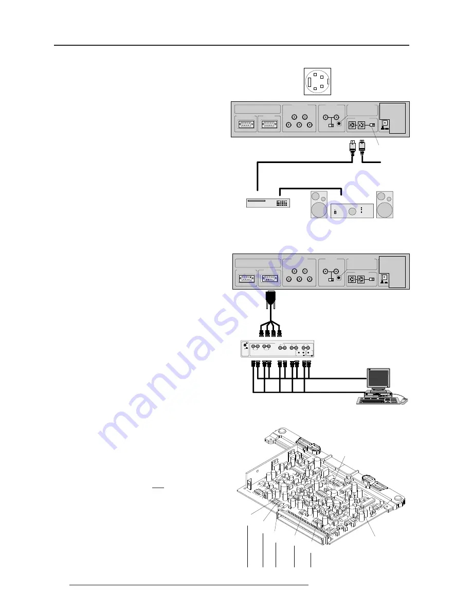
Connecting a S-Video (or Composite Video)

source to Port 2

Separate Y-luma/C-chroma signals for higher quality playback of

Super VHS signals can be connected to Port 2 . A composite video

signal can also be connected to this port.

To select the S-video input :

Press the 

digit button 2 

on the RCU or the local keypad

.

In case of using Port 2 for connecting the Composite Video, the

selection of this source have to be done inside the "Picture Tuning"

menu. Please refer to the Owner's Manual.

75 

W

 Termination Switch for S-video

Terminate the S-video input of the projector using the 75 

 switch next

to the S-video input when the projector operates alone or when the

projector is the last unit in a loop-through configuration.

The switch is set to "ON" : signal terminated.

The switch is set to "OFF": signal not terminated.

Connecting a RGB Analog source to Port 3

Connect a  RGB Analog signal via an interface (e.g. RGB 120MHz

interface, part number 98 26570) to Port 3.  RGB analog input with

automatic sync detection (Separate H and V sync inputs, with

composite sync input or with sync signals on green) and automatic

polarity detection.

Pin configuration of the D9 (male) connector of the Analog input :

1

not connected

2

ground RGBS

3

RED

4

GREEN

5

BLUE

6

ground RGBS

7

ground RGBS

8

Horizontal /composite sync

9

Vertical sync

To select the RGB analog Input :

Press the

 digit button 3 

on the RCU or the local keypad

.

S1 Force Negative Sync

(ON=yes)

R81

Hsync

R101

Vsync

R41

(Blue)

R21

(Green)

R1

(Red)

S2 Blue in Green (ON=yes)

Line termination 75 

 resistors

Locations of the Termination Resistors and Switches

on the RGB Input Auto Sync Tracking Module

When changing a switch position or removing a resistor, turn off the

projector and unplug the power cord from the wall outlet.

75 

W

 Termination resistors

In case of chaining (loop-through) the projectors, the 75

 line

termination resistors must be removed from the  RGB Input Auto Sync

Tracking Module when the projector is NOT the last unit in the chain.

In case of a stand-alone projector, do not remove the resistors.

75 

Ω 

resistors on the module :

line terminated.

75 

  resistors removed

:

line not terminated.

1

2

3

4

4 pin connector configurations:

For S-video:

Pin 1: earth(ground) luminance

Pin 2: earth(ground) chrominance

Pin 3: luminance signal(Y)

1Vpp 

±

3dB

Pin 4: chrominance signal(C)

300mVpp 

±

3dB

For video:

Pin 1: earth(ground) video

Pin 2: not connected

Pin 3: video signal

Pin 4: not connected

RKP

2)) 21

3257

9,'(2

3257

5*%+9

&RPS+V\QF9V\QF

5

*

%

3257

3257

5(027(

&20081,&$7,21

352-(&72502'(

32:(50$,16

3257

69,'(2

RKP

21

2))

*5((1RSHUDWLRQDO

5('VWDQGE\

9&569+6

$XGLRDPSOLILHU

/XPD&KURPD

WRQH[WSURMHFWRURU

WRDPRQLWRU

75 

 Termination

Switch

RKP

2)) 21

3257

9,'(2

3257

5*%+9

&RPS+V\QF

9V\QF

5

*

%

3257

32575(027(

&20081,&$7,21

352-(&72502'(

32:(50$,16

3257

69,'(2

RKP

21

2))

*5((1RSHUDWLRQDO

5('VWDQGE\

,13

,13

5

*

%

+

9

,1387

$1$/2*,17(5)0+]

21

2))

LQYHU

RKPWHUP

361

RGB 120MHz interface

Summary of Contents for R9002250

Page 1: ...R9002250 R9002259 INSTALLATION MANUAL DATA 1209s...

Page 2: ...BARCO PROJECTION SYSTEMS Date 040698 Art No R5975718 R9002250 R9002259 INSTALLATION MANUAL DATA 1209s Rev 00...

Page 3: ...ice Produced by BARCO NV June 1998 All rights reserved Trademarks are the rights of their respective owners BARCOnv ProjectionSystems Noordlaan5 B 8520Kuurne Belgium Tel 32 56 368211 Fax 32 56 351651...

Page 4: ...n switches 4 2 Horizontal scan switches 4 3 Vertical scan switch 4 3 PROJECTORSET UP Setting the projector address 5 2 Power upmode 5 3 Operational mode 5 3 Stand By mode 5 3 Baud Rate for communicati...

Page 5: ...source selector to the projector 7 4 Connecting a VS05 source selector to the projector 7 4 Connecting an IR Remote Receiver 800 to the projector 7 4 INSTALLATIONADJUSTMENTMODE Access to Installation...

Page 6: ...tch over from 230Vac to 120 Vac or from 120Vac to 230 Vac If you are not sure of the type of AC power available consult your dealer or local power company 2 This product is equipped with a 3 wire grou...

Page 7: ...ing to qualified service personnel under the following condi tions A When the power cord or plug is damaged or frayed B If liquid has been spilled into the equipment C If the product has been exposed...

Page 8: ...type CEE7 or ANSI 73 11 1 Owner s Manual 1 Installation Manual 1 Adjustment Manual IRIS To open the banding around the carton pull out the clip as shown below Take the projector out of its shipping ca...

Page 9: ...050698 Projector dimensions in mm Dimensions m m inch L1 1174 46 2 L2 1014 39 9 L3 1000 39 37 L4 735 28 9 L5 110 4 33 L6 265 10 43 W1 782 30 8 W2 665 26 2 H1 355 13 9 H2 315 12 4 H3 219 8 62 H4 101 3...

Page 10: ...he room to the point where there is just sufficient light to read or write comfortably Spot lighting is desirable for illuminating small areas so that interference with the screen is minimal Which scr...

Page 11: ...ter 8 for details Where to install the projector To indicate a correct installation position it is necessary to know The distance from projector to ceiling in case of Ceiling mounted or the distance f...

Page 12: ...cover is not supported with locking hinge Open with care and support the cover with your hand Lock screws Removing the top cover During some installations it will be convenient to remove the top cove...

Page 13: ...tection plate For opening the projector s top cover see Access to controls WARNING TURN OFF PROJECTOR AND UNPLUG THE POWER CORD BEFORE CHANGING THE SCAN DIRECTION Open the top cover and remove it from...

Page 14: ...e vertical scan inversion switch to the correct position After setting the scan switches close the metal protection plate and secure it with the retaining screws Close the top cover and reconnect the...

Page 15: ...ETEALLBLOCKS CHANGEPASSWORD CHANGELANGUAGE RUNTIME DYNAMICASTIGMATISM MORE Select with or then ENTER EXIT to return Proj address 001 Soft Version 6 00 Config Ceiling Front Baudrate PC 9600 Text ON Ser...

Page 16: ...of the frame Loosen the 3 screws on the rear side of the metal frame Lift up the metal cover plate and pivot to the lens side The controller is mounted on the back side StdBY MAIN P OWER P ROCE SSOR C...

Page 17: ...l value The sum of the values associated to those DIP switches gives the address As shown in the table if Switch No 1 is set to ON it represents a decimal value of 128 Switch No 2 for 64 Switch No 3 f...

Page 18: ...h a computer The communication speed between the projector and the computer has 8 possible settings With DIP Switch No 6 No 7 and No 8 of the 8 DIP switches on the controller board labelled as Baud ra...

Page 19: ...or more information about password setting and reprogramming the pass word see Installation adjustment When the password menus are disabled adjust mode is unpro tected the adjust mode can be selected...

Page 20: ...the terminals in your plug proceed as follows The yellow green wire is ground and must be connected to the terminal in the plug which is marked by the letter E or by the safety earth symbol or colored...

Page 21: ...c or vice versa is possible Follow the procedure as described below to adapt the voltage WARNING turn off the projector and be sure the AC Power Cord is unplugged from the wall outlet before starting...

Page 22: ...l white image When the projector is set to start up with a full white image the Projector warm up menu will be displayed for 30 seconds Start up with Warm up period If no action is taken a white image...

Page 23: ...th the following text will be displayed Please use EXIT to leave this procedure Start up without Warm up period IfEXITispressed thewarmupperiodwillbeskippedandtheprojector is immediately ready for use...

Page 24: ...evel sync on Green or with separate Tri 4 5 RGB with Tri level sync 7 level sync or with separate Horizontal and Vertical Tri level sync R Y Y B Y with Tri level sync on Y or with separate Tri level s...

Page 25: ...9 Vertical sync To select the RGB analog Input Press the digit button 3 on the RCU or the local keypad S1ForceNegativeSync ON yes R81 Hsync R101 Vsync R41 Blue R21 Green R1 Red S2BlueinGreen ON yes L...

Page 26: ...onnected to the projector via Port 4 5 The projector automatically detects where the sync signal is located An interface is recommended when connecting a computer and local monitor to the projector BA...

Page 27: ...VS05 source selector to the projector The VS05 can switch up to 5 Composite Video sources 3 S Video Sources and 1 RGB analog or component Video source to the projector In addition the audio signal ass...

Page 28: ...active you will be requested to enter the 4 digit password Enter the digits with the numeric keys on the RCU or the local keypad Installation Raster Centering Projector Distance Optical Lens Focusing...

Page 29: ...rear end of the lens and rotating the lens barrel until the center of the image is clearly focused The corners of the projected image are focused by loosening the wing nut at the front end of the len...

Page 30: ...the middle of the CRT faceplate Press ENTER to activate the raster on the Red CRT faceplate Shift the Red raster with the control stick until the raster is centered on the CRT faceplate Press ENTER t...

Page 31: ...ON ANGLE ADJUSTMENT Align crosshairs ENTER continue EXIT to return Press ENTER to start the CRT angle adjustment procedure Press ENTER to continue with the crosshairs alignment Press EXIT to return to...

Page 32: ...to return to the CRT projection angle adjustment CRT PROJECTION ANGLE ADJUSTMENT Align crosshairs ENTER continue EXIT to return Blue crosshair Green crosshair Move the blue CRT to the out side away f...

Page 33: ...r Equalize now diagonally the focus from left top to right bottom by turning screw A4 located under the green lens 5 5 1 8 51 1 7 2 867 6 03 8 255 7 216 7 2 567 226 1 7 255 6321 1 6 85 7 1876 72 6 03...

Page 34: ...IRIS Select with or then ENTER EXIT to return After finishing the Installation Adjustment Procedures the main menu returns on the screen You are now able to start the alignment procedure for the proj...

Page 35: ...r placement on lower support a Projector placement on support b Location of controls for projector position correction 3 Mounting instructions of the cord to lift up the projector a Mounting the cord...

Page 36: ...Appendix A BARCO ceiling mount support A 2 5975718 BARCODATA 1209s 050698 Projector position corrections Water level adjustment Projector axis adjustment D C...

Page 37: ...ut If not follow the next procedure to adjust the G2 1 open both metal cover by loosening the retaining screws on both sides and pivot the covers to the front side of the projector 2 adjust the G2 pot...

Page 38: ...efactorypreset To carry out the Blue Gamma Correction 1 Push the control disk up or down to highlight the item BLUE GAMMA CORRECTION in the menu and then press ENTER If EXIT is pressed the projector w...

Page 39: ...adjust the Blue Midlights a text box with a bar scale 0 16 will be displayed to visualise the magnitude of the correction 5 Press ENTER to return to the Gamma Corrections menu GAMMA CORRECTIONS BLUE G...

Page 40: ...IL STD 1341 NATIONAL FIRE PROTECTION ASSOCIATION STD 704M SIGNAL TRESHOLD LIMIT VALUE Units TRESHOLD LIMIT VALUE Units BASE METAL ALLOYS METALLIC COATINGS FILLER METAL PLUS COATING OR CORE FLUX OTHERS...

Page 41: ...E RESULTS TO BE OBTAINED FROM THE USE THEREOF VENDORASSUMESNORESPONSABILITYFORINJURYTOVENDEEORTHIRDPERSONSPROXI MATELY CAUSED BY THE MATERIAL IF REASONABLE SAFETY PROCEDURES ARE NOT AD HERED TO AS STI...

Reviews: